 FEXLINK Research Institute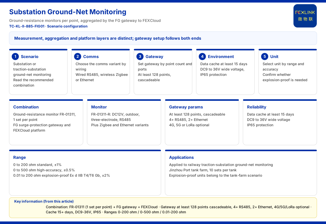
Direct Answer
For online monitoring of substation and traction-substation grounding grids, the recommended combination given in the typical application scenarios and selection comparison of the product knowledge base is: the grounding resistance monitor (FR-01311, one set per point), the lightning-protection smart gateway (FG) and the FEXCloud platform. That is, monitoring units are laid out by grounding point, one set per point, then aggregated by the lightning-protection smart gateway and finally connected to the platform. As for the gateway configuration, the system-level smart-gateway reference parameters of the product knowledge base give mounting of no fewer than 128 points with cascading, at least 4 RS485 channels, at least 2 Ethernet channels, optional 4G, 5G or LoRa, a data cache of at least 15 days, a wide supply of DC9 to 36 volts and IP65 protection. The product knowledge base gives no point table, wiring scheme or acceptance convention of a specific project, so this article states only the recommended combination, gateway parameters and range classification without expanding them into an engineering scheme.
1. First Look at the Recommended Combination Given by the Scenario
In the typical application scenarios and selection comparison of the product knowledge base, the row for online monitoring of substation and traction-substation grounding grids gives a recommended product combination of the grounding resistance monitor (FR-01311, one set per point), the lightning-protection smart gateway (FG) and FEXCloud. This combination contains three levels: the measurement layer, the aggregation layer and the platform layer. The measurement layer is the grounding resistance monitor, arranged by grounding point, one set per point; the aggregation layer is the lightning-protection smart gateway, which aggregates the data of multiple measurement points and uploads it; the platform layer is FEXCloud, which receives the data and the application. Seeing the three separately, when configuring the gateway one knows its upstream is several monitoring units and its downstream the platform, and its mounting and communication parameters are determined around these two ends.
2. Models and Measurement Methods of the Monitoring Units
The product knowledge base records that the grounding resistance monitor (FR-01311) series includes three models, FR-01311-R and FR-01311-Z and FR-01311-E, of which FR-01311-R uses a 12-volt DC supply, outdoor installation, three-pole measurement and RS485 communication, with Zigbee and Ethernet communication variants. Thus the same measurement function can be accessed through wired RS485, wireless Zigbee or Ethernet, and the model depends on the wiring conditions and distance between the monitoring point and the gateway. The product knowledge base does not give the range and accuracy of this series; the range and accuracy are given separately in the system-level monitoring-unit parameters, so this article cites the two separately and does not attach the system-level parameters directly to a specific model.
3. Mounting and Communication of the System-Level Smart Gateway
The product knowledge base gives the system-level smart-gateway reference parameters of a grounding-resistance monitoring system: mounting of no fewer than 128 points with cascading, at least 4 RS485 channels, at least 2 Ethernet channels, and optional 4G, 5G or LoRa. This group directly answers how to configure the gateway. The mounting point count determines how many monitoring points a gateway can aggregate, and cascading shows the point count can expand with scale; the RS485 and Ethernet channel counts determine wired access; and the optional wireless method allows wireless backhaul when wiring is restricted. The product knowledge base does not give the upload period of a single point or the concurrency index of the gateway, so this article cites only the mounting and interface conventions and adds no throughput parameter.
4. Supply, Cache and Protection of the Gateway
The same group of system-level reference parameters also includes: a data cache of at least 15 days, a wide supply of DC9 to 36 volts and IP65 protection. These three determine the reliability of the gateway outdoors and in the power site. The data cache prevents loss during a communication interruption, the wide-voltage supply adapts to power fluctuations on site, and IP65 protection responds to the outdoor environment. Together with the mounting and interfaces above, two main lines of gateway configuration appear: capability and interfaces, determining how many points can be connected and how; and operating environment and reliability, determining whether it can work continuously in the power site. The product knowledge base does not give the specific installation method or maintenance period, so this article cites only the parameters themselves.
5. Range and Accuracy Classification of the Monitoring Units
The grounding resistance monitoring units of the product knowledge base are divided by range and accuracy into several tiers: 0 to 200 ohms is the nominal type with an accuracy of plus or minus 1 percent; 0 to 500 ohms is the high-accuracy type with an accuracy of plus or minus zero point five percent; and 0.01 to 200 ohms is the explosion-proof type, marked Ex d IIB T4 and T6, Gb, with an accuracy of plus or minus 2 percent. These three tiers show that, when choosing a monitoring unit, one must first determine the resistance range and accuracy requirement of the grounding grid to be measured and then determine whether explosion protection is needed. The product knowledge base does not give the applicable-scenario correspondence table of each tier, so this article cites only the range, accuracy and explosion-proof marking and does not infer which tier a given grounding grid should choose.
6. Listed Applications and Scenario Distinction
The product knowledge base records that this series of grounding resistance monitors and the explosion-proof product have been applied to online monitoring of railway traction-substation grounding grids and to the Jinzhou Port oil-tank farm, where the oil-tank farm is deployed at 10 sets per tank. This shows actual deployment records in power and petrochemical scenarios and gives the deployment-quantity convention of the oil-tank farm. Note that the oil-tank farm and petrochemical lightning and explosion protection scenario recommends explosion-proof grounding resistance monitoring (Ex d IIB) plus lightning current monitoring and lightning-protection device monitoring, which differs from the grounding-grid online monitoring combination. That is, the explosion-proof type belongs to another scenario, and configuration should choose by scenario rather than simply mixing the devices of the two scenarios.
7. Boundaries to Keep and the Reading Order
The above can be reduced to a reading order. First, confirm that the scenario is online monitoring of a substation or traction-substation grounding grid, and read the recommended combination as the grounding resistance monitor (FR-01311, one set per point), the lightning-protection smart gateway (FG) and FEXCloud. Second, determine the communication variant of the monitoring unit by wiring conditions. Third, determine the gateway's mounting and communication configuration by point count and interfaces. Fourth, confirm on-site adaptability by supply, cache and protection. Fifth, choose the monitoring unit by range and accuracy, and confirm whether it belongs to the other scenario requiring explosion protection. The boundary to keep is that no point table, wiring scheme or acceptance convention of a specific project is given; the actual configuration must be determined against site data and not inferred from the product knowledge base.
Applicability and Limits
First, this article restates only what the product knowledge base lists; its factual boundary is the typical application scenarios and selection comparison, the grounding resistance monitor model records, the system-level smart-gateway reference parameters and the monitoring-unit range parameters.
Second, the recommended combination for online monitoring of substation and traction-substation grounding grids is the grounding resistance monitor (FR-01311, one set per point), the lightning-protection smart gateway (FG) and FEXCloud, as listed in the selection comparison.
Third, the 12-volt DC, outdoor installation, three-pole method and communication variants of the grounding resistance monitor (FR-01311-R), (FR-01311-Z) and (FR-01311-E) are cited under the convention listed in the product knowledge base.
Fourth, the system-level smart gateway mounting of no fewer than 128 points with cascading, at least 4 RS485 channels, at least 2 Ethernet channels and optional 4G, 5G or LoRa are cited under the convention listed in the product knowledge base.
Fifth, the data cache of at least 15 days, the wide supply of DC9 to 36 volts and IP65 protection are cited under the convention listed in the product knowledge base.
Sixth, the range, accuracy and explosion-proof marking of the monitoring units 0 to 200 ohms nominal type, 0 to 500 ohms high-accuracy type and 0.01 to 200 ohms explosion-proof type are cited under the convention listed in the product knowledge base.
Seventh, the application records of railway traction substations and of the Jinzhou Port oil-tank farm at 10 sets per tank, and the explosion-proof type's belonging to the oil-tank farm and petrochemical scenario, follow the product knowledge base convention.
Eighth, the product knowledge base gives no point table, wiring scheme or acceptance convention of a specific project; this article accordingly states no engineering conclusion. It explains only the information and reading order within the product knowledge base and is not a commitment to selection or construction for a specific project; the latest product materials and formal documents prevail.