 微物联研究院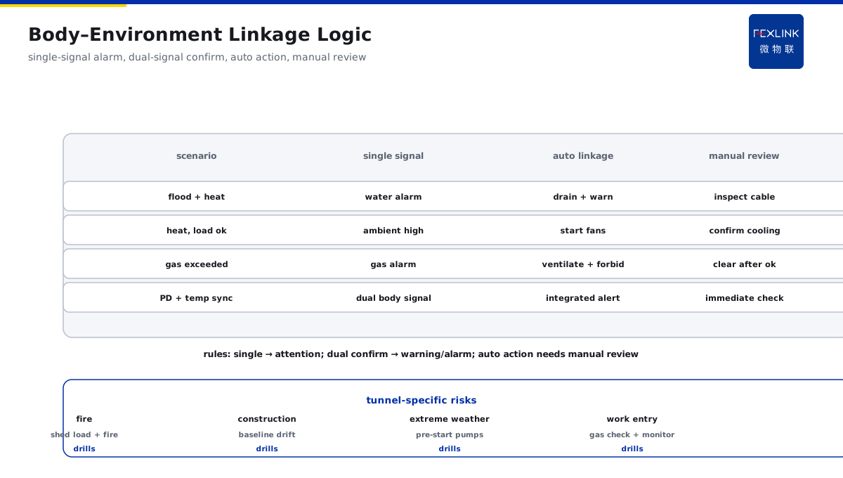
Direct Answer
How should an online monitoring scheme be designed for a long-distance cable tunnel? The answer: integrate two lines — "cable body + environment." The body line uses distributed fiber-optic temperature sensing for continuous measurement, with PD monitoring added at key nodes; the environment line monitors water level, temperature/humidity, and harmful gases; all data converges at an edge gateway before upload to the platform. The key is "body monitoring + environment linkage" — an abnormal water level links to ventilation and warnings, forming integrated alerts.
An underground cable tunnel in a city is 3.2 km long. The original scheme piled up scattered temperature, water-level, and gas devices that each ran independently. Redone with the two-line scheme: the body line laid distributed fiber-optic temperature sensing along the whole tunnel (continuous temperature profile), with PD monitoring at 3 intermediate joints; the environment line placed one node per 200 m (water level + temperature/humidity + harmful gases); data converged at the ESX edge gateway before upload. After heavy rain, a local section of the tunnel flooded; the water-level node alarmed and automatically linked the drain pumps and entrance warning, while the platform checked the fiber temperature for that section — finding the cable temperature in the flooded section rising in parallel. Water removal and cable inspection were arranged early, avoiding a water-immersion fault. The core of a cable-tunnel monitoring scheme is the "body + environment" two-line integration: the body line watches cable health, the environment line watches tunnel risk, and only their linkage forms integrated alerts.
Because:
- Tunnel environments are complex with many monitored objects: cable body (temperature/PD) + environment (water/temperature-humidity/gas) — missing either line leaves blind spots;
- Distributed fiber-optic sensing covers the whole route: point sensing has blind spots; fiber gives a continuous temperature profile;
- Environmental change directly affects cables: flooding → cable moistens and heats; high temperature → derated ampacity — the environment line is the "outpost" of the body line;
- Linkage is what produces integrated alerts: water-level anomaly + temperature rise, dual-signal confirmation, is not an isolated alarm.
Key insight: cable-tunnel monitoring is two-line integration, not equipment assembly. Body line + environment line + edge convergence + linkage logic — with all four, tunnel risk is fully visible.
A cable tunnel monitored normally; after a construction disturbance, the temperature in the sandwich layer slowly rose. The platform found the abnormal temperature trend and linked an inspection — a local ventilation duct had been damaged by construction, leaving the cable running in a stuffy, hot environment. Ventilation was restored in time, avoiding long-term high-temperature aging. An environment-line anomaly is often the "outpost signal" of a body problem — temperature rises before the fault appears.
1. Body Monitoring Line Configuration
Line one: how the cable body is monitored.
Distributed fiber-optic temperature sensing:
- Principle: a sensing fiber laid along the cable, one temperature point per meter (continuous temperature profile);
- Coverage: the full tunnel (continuous, no blind spots);
- Role: cable surface temperature distribution, hotspot locating, early detection of overload/contact problems;
- Reference: temperature thresholds + joint-vs-adjacent ΔT (hotspot vs normal section).
PD monitoring (key nodes):
- Positions: intermediate joints, terminations, cable crossings (defect-prone points);
- Method: PD sensors (TEV/UHF);
- Role: early signal of insulation defects (joint partial discharge);
- Reference: PD trend (grows with load = real defect).
Body-line configuration principles:
- Fiber temperature sensing covers the whole tunnel;
- PD monitoring at key nodes (joints/terminations);
- Continuous body data (temperature profile + PD trend);
- Graded thresholds (normal/attention/warning/alarm).
Body-line value:
- Continuous profile: hotspots cannot hide (point sensing misses them);
- Trend criteria: temperature/PD trends show degradation;
- Locating capability: precise hotspot position (fast investigation).
Key insight: the body line watches cable health. Fiber sensing full coverage + PD at key nodes — temperature profile + PD trend keep cable condition continuously visible.
2. Environment Monitoring Line Configuration
Line two: how the tunnel environment is monitored.
Water-level monitoring:
- Positions: tunnel low points, sump wells, entrances/exits (flood-prone points);
- Role: flooding risk (immersion → moistened cable → insulation drop);
- Reference: graded water-level thresholds (warning/alarm/linkage pumping);
- Density: one point per 100–200 m (per tunnel gradient).
Temperature/humidity monitoring:
- Positions: multiple points in the tunnel (sectional monitoring);
- Role: high temperature → derated ampacity, faster aging; high humidity → insulation moistening;
- Reference: temperature threshold + humidity threshold (e.g., watch at 40 °C / 80% RH);
- Density: one node per 200 m.
Harmful-gas monitoring:
- Positions: inside the tunnel (safety check before personnel entry);
- Role: CO, CH₄, H₂S, etc. (personnel safety + explosion risk);
- Reference: gas-concentration thresholds (alarm → ventilate / forbid entry);
- Density: one node per 200–300 m.
Environment-line configuration principles:
- Sectional monitoring (the tunnel is long; cover by sections);
- Water level is the priority (the most common tunnel risk);
- Gas linked to personnel safety (check before tunnel entry);
- Continuous environment data (trends visible).
Key insight: the environment line watches tunnel risk. Water level + temperature/humidity + harmful gas — three sectional monitoring lines leave no environmental risk uncovered.
3. Edge Convergence and Upload
How data converges: the edge gateway is the hub.
Edge-layer duties:
- Data convergence: body line (fiber temperature + PD) and environment line (water/temperature-humidity/gas) uniformly connected;
- Local baseline: per-section normal baselines (temperature/water/gas);
- Local pre-judgment: over-baseline pre-judgment; abnormal data uploaded with priority;
- Offline capability: local judgment continues during communication outage (offline watch).
Upload architecture:
- Field devices → edge gateway (ESX, local convergence) → platform (cloud / on-premises server);
- Communication: fiber ring network (reliable in tunnels) + 4G/5G backup;
- Data frequency: body continuous (seconds), environment on demand (minutes);
- Unified platform management (one view of the whole tunnel).
Long-distance power and communication:
- Power: sectional supply (low-voltage power by section) + UPS assurance;
- Communication: fiber ring (self-healing at break points; one section down, another reroutes);
- Backup: wireless backup (4G fallback when fiber fails);
- Reliability: power/communication dual redundancy (tunnel environments cannot be neglected).
Meaning of convergence:
- Unified data (body + environment on one view);
- Localized judgment (warning even when offline);
- Platform focus (trend analysis, linkage disposition).
Key insight: edge convergence is the data hub. Body + environment unified, local baseline, offline capability, dual redundancy — reliable convergence, uninterrupted judgment.
4. Body–Environment Linkage Logic
Core value: how the two lines link.
Linkage scenarios:
- Flooding + temperature rise: water-level alarm → auto-start drain pumps → simultaneously check that section's cable temperature (confirming moisture-induced heating);
- High temperature + normal load: high ambient temperature → ventilation linkage (start fans) → cable cooling;
- Gas exceeded + personnel working: gas alarm → ventilation + warning + forbid entry;
- PD + temperature in sync: body dual-signal confirmation (insulation defect + heating) → integrated alert.
Linkage-logic design:
- Signal confirmation: single-signal alarm (attention) → dual-signal confirmation (warning/alarm);
- Automatic actions: drain pumps, fans, warnings (auto linkage);
- Human intervention: manual review after any automatic action (on-site confirmation);
- Integrated alerts: multi-signal integrated output (not isolated alarms).
Linkage-rule examples:
- Water-level warning + that section's temperature normal → attention (observe drainage);
- Water-level alarm + that section's temperature rising → linked drainage + cable inspection (integrated alert);
- Gas alarm → ventilation linkage + forbid entry (safety first);
- PD alarm + temperature rising → integrated alert (immediate inspection).
Value of linkage:
- Isolated alarms → integrated alerts (more accurate judgment);
- Automatic actions → fast response (drainage/ventilation automatic);
- Body and environment corroborate each other (no false alarms, no misses).
Tunnel-specific risk responses:
- Cable fire: rapid temperature rise + smoke monitoring → auto-shed that section's load + fire linkage + personnel-evacuation warning;
- Construction disturbance: external work affecting the tunnel → vibration/displacement monitoring + temperature-baseline drift warning;
- Extreme weather: water-level pre-judgment before heavy rain → drain pumps pre-started + tunnel inspection reminder;
- Operations work: personnel entering the tunnel → gas check + ventilation confirmation + work-zone monitoring (safety closed loop);
- Special contingency plans: each risk class has corresponding linkage rules and disposition flow (drilled regularly).
Key insight: linkage is the key to integrated alerts. Single-signal alarm, dual-signal confirmation, automatic action, manual review — the two lines corroborate, and judgment is accurate.
5. Scheme Implementation Points
How the scheme lands: implementation points.
Implementation steps:
- Tunnel survey: length, gradient, low points, ventilation points;
- Design configuration: fiber sensing + PD + environment-node placement design;
- Equipment installation: fiber laying, sensor mounting, power/communication deployment;
- Commissioning: data connection, baseline establishment, linkage-rule configuration;
- Acceptance trial run: alarm verification, linkage verification, false-alarm-rate assessment.
Baseline establishment:
- 1–2 weeks of normal-operation recording (temperature/water/gas baselines);
- Sectional baselines (sections differ in environment);
- Seasonal correction (different summer high-temperature baselines);
- Linkage thresholds set per baseline + procedures.
Acceptance metrics:
- Data online rate (target 99%+);
- Fiber temperature profile complete (no blind spots);
- Linkage-action correctness (linkage scenarios verified);
- False-alarm rate (target < 20%).
Operations requirements:
- Regular inspection (device status, fiber integrity);
- Platform monitoring (trends, alarms, closure);
- Linkage testing (periodic trigger verification);
- Emergency response (flooding/gas/fire contingency plans).
Data application and review:
- Monthly temperature-profile analysis: hotspot-position changes (contact-degradation trend);
- Water-level event review: flood-prone sections (drainage-system optimization);
- Alarm distribution: type/location/period (tunnel risk profile);
- Linkage-effectiveness assessment: automatic-action correctness, response timeliness;
- Threshold optimization: continuous calibration on operating data (false-alarm rate falls).
Key insight: implementation points make the scheme landable. Survey → design → install → commission → accept, five steps — baselines, linkage, and acceptance metrics all clear.
6. Product Landing: Cable-Tunnel Monitoring Scheme
FEXLINK products bring the cable-tunnel monitoring scheme to the field:
- EST Multi-Channel Temperature Controller: distributed temperature nodes / fiber temperature-sensing access, temperature-profile monitoring;
- ESX Edge Computing Gateway: unified convergence of body + environment data, local baselines, offline judgment;
- Digital Electrical Intelligent Supervision System: platform integrated alerts, linkage disposition, work-order closure;
- Environment monitoring nodes: water level / temperature-humidity / harmful gas (configured per tunnel section);
- Linkage logic: flooding → drain pumps, high temperature → fans, gas → ventilation warning (automatic + manual review).
Design principle in one sentence: turn "equipment assembly" into "two-line integration." Body line + environment line + edge convergence + linkage logic — tunnel risk comprehensively visible.
7. Common Scheme-Design Mistakes
- Body only, no environment: temperature sensing only. Consequence: flooding/high-temperature environmental risks missed. Correct: body + environment, two lines.
- Point sensing with blind spots: only point temperature sensors. Consequence: hotspots missed. Correct: distributed fiber continuous sensing.
- Devices each on their own: water, gas, and temperature alarm independently. Consequence: isolated alarms, poor judgment. Correct: unified convergence + linkage logic.
- Neglecting long-distance power/communication: single points for power and comms. Consequence: losing contact in deep tunnel sections. Correct: sectional power + fiber ring + backup.
- Linkage without human review: ignoring after automatic action. Consequence: automatic misaction unknown. Correct: manual review after any linked action.
Scope and Limitations
This article provides an overall framework for online monitoring of cable tunnels and sandwich layers (body monitoring line, environment monitoring line, edge convergence, linkage logic, implementation points) for online-monitoring project design on long-distance cable tunnels, cable sandwich layers, and utility-tunnel cable bays. Monitoring density and node quantity should be adjusted to tunnel length, environment, and budget; linkage actions (drain pumps, fans, etc.) involve safety operations and must be configured per procedures and tested periodically; harmful-gas monitoring must be configured per relevant safety procedures; tunnel work must be performed by qualified personnel. Online monitoring data is managed uniformly through the platform to form trend alerts. All cases are anonymized (a certain urban underground tunnel) and do not refer to any specific customer.