 FEXLINK Research Institute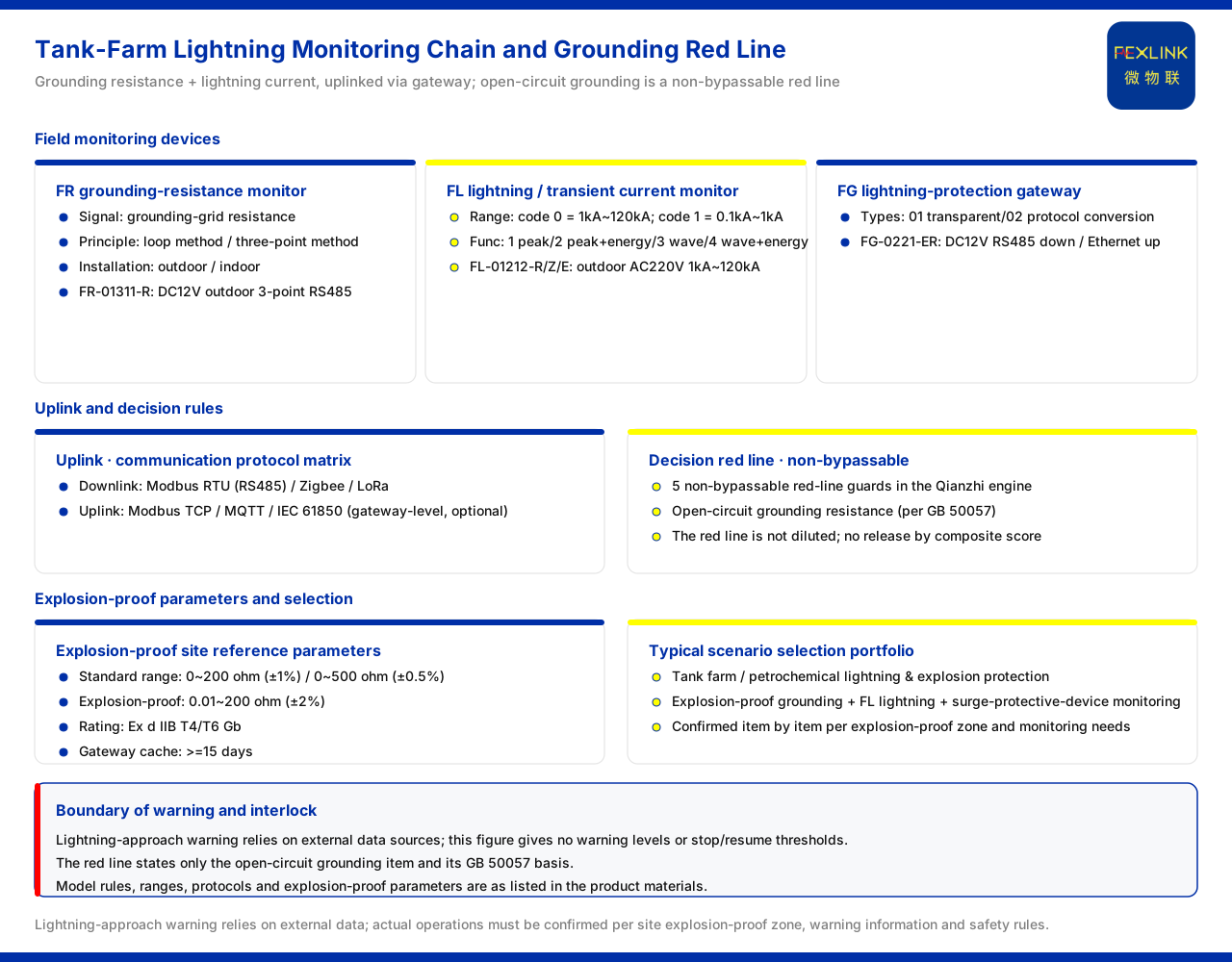
Oil-depot lightning early warning and operation interlock: under what conditions loading should be stopped
Direct answer
The decision to stop loading should not rest on experience alone but on the grounding state of the yard and lightning-current data. The product knowledge base provides the monitoring-side equipment and rule basis for this class of yard. The FR grounding resistance monitor (e.g. FR-01311-R) is responsible for collecting the grounding-network resistance, its signal-acquisition position being the grounding-network resistance, its detection principle split into the loop method and the three-point method, and its installation method into outdoor and indoor; the FL lightning current / transient current monitor (e.g. FL-01212-R) is responsible for lightning-current and transient-current monitoring; the FG lightning-protection smart gateway (e.g. FG-0221-ER) is responsible for data uplink and protocol conversion. At the rule level, an abnormal open circuit of grounding resistance is listed as one of the red lines that cannot be bypassed, on the basis of GB 50057. On reference parameters, grounding resistance monitoring covers 0 to 200Ω (accuracy ±1%), 0 to 500Ω (accuracy ±0.5%) and an explosion-proof type of 0.01 to 200Ω (accuracy ±2%, explosion-proof grade Ex d IIB T4/T6 Gb); the data caching of the smart gateway can reach 15 days or more, adapted to petrochemical explosion-proof yards. The selection combination for tank-farm and petrochemical lightning-protection and explosion-proof scenarios is explosion-proof grounding resistance monitoring, lightning-current monitoring and surge protective device monitoring. It should be noted that lightning approach warning itself depends on the access of external data sources, and this article gives no specific warning level or stop/resume threshold.
1. What on-site data the stop-loading decision needs
When oil-depot loading operations meet thunderstorms, whether to stop operations and when to resume is a judgement involving safety and continuity of operations. For this judgement to be executable, two kinds of on-site data are needed: one is the grounding state, that is, whether the grounding-network resistance is within the normal range; the other is lightning-related data, that is, whether lightning current or transient current has occurred in the yard and at what magnitude. The product knowledge base provides monitoring equipment for these two kinds of data respectively: the grounding resistance monitor handles the former and the lightning current and transient current monitor the latter, and the two are aggregated upward through the lightning-protection smart gateway. Building the stop-loading decision on these data is the precondition for turning it from subjective experience into a checkable basis; as for the specific warning level and stop/resume threshold, they still depend on external lightning-warning data and the on-site management system, and this article does not set them.
2. Grounding state: the grounding resistance monitor
The product knowledge base records that the signal-acquisition position of the grounding resistance monitor is the grounding-network resistance, that the detection principle is divided into the loop method and the three-point method, and that the installation method is divided into outdoor and indoor. The example model FR-01311-R is supplied at DC12V, installed outdoors, measured by the three-point method, and communicates via RS485. Linking the model fields with the detection principle shows that during selection the measurement method and the installation environment can be confirmed according to site conditions: different grounding-network conditions suit different detection principles and installation methods, while outdoor or indoor installation affects the deployment position of the device. Grounding resistance monitoring answers the basic question of the grounding-network resistance; once its value enters the monitoring chain, it can serve, together with lightning-current monitoring data, as an observation basis for the state of the yard.
3. Lightning-current monitoring: range tiers and function tiers
Lightning-current and transient-current monitoring is carried by the lightning current / transient current monitor. The product knowledge base records that its detection range is divided into two tiers: one is 1kA to 120kA, the other is 0.1kA to 1kA. The function is divided into four classes: peak, peak plus energy, waveform, and waveform plus energy. The FL lightning current / transient current monitor (e.g. FL-01212-R, FL-01212-Z, FL-01212-E) is installed outdoors, supplied at AC220V, and corresponds to the 1kA to 120kA detection range. The range tier corresponds to the magnitude of lightning current to be captured, and the function tier to the type of information to be recorded; during selection one should choose according to the expected lightning-current level of the yard and the waveform information to be mastered, rather than assuming in general terms that a larger range or more functions are always better.
4. Data uplink: gateway and protocol
The grounding and lightning-current data collected on site must be aggregated upward through the gateway. The product knowledge base records that the gateway types of the lightning-protection smart gateway are divided into transparent transmission and protocol conversion, and that the example model FG-0221-ER is supplied at DC12V, with RS485 downstream and Ethernet upstream. At the protocol level, in the communication protocol matrix of the product knowledge base, the device downstream supports Modbus RTU (RS485), Zigbee and LoRa, and the device upstream supports Modbus TCP, MQTT and the optionally configured IEC 61850 (at gateway level). The protocol matrix describes the channel types for data access, while the gateway determines how on-site data enters the upper system.
5. Red-line basis: an abnormal open circuit of grounding resistance
At the judgement level, the Qianzhi engine of the product knowledge base has 5 red-line guards that cannot be bypassed, one of which addresses an abnormal open circuit of grounding resistance, with GB 50057 as its basis. Placed in the stop-loading scenario, its meaning is that an abnormal open grounding-resistance circuit is a precondition problem that cannot be diluted by other indicators. Even if other monitoring data is normal, once the grounding state shows an open circuit, operations cannot be released on the grounds that the composite score is still acceptable. That is, the role of the red-line guard in the operation interlock is not to raise the weight of a certain score but to draw a boundary that cannot be crossed. This article states only this one red line and its basis; it does not infer the content of the remaining red lines.
6. Reference parameters and selection for explosion-proof yards
An oil depot is a yard requiring explosion-proof consideration, and the product knowledge base provides explosion-proof related parameters for it. Among the reference parameters of the grounding resistance monitoring system, besides the conventional 0 to 200Ω (accuracy ±1%) and 0 to 500Ω (accuracy ±0.5%), there is an explosion-proof type of 0.01 to 200Ω (accuracy ±2%) with an explosion-proof grade of Ex d IIB T4/T6 Gb; the data caching of the smart gateway can reach 15 days or more, adapted to petrochemical explosion-proof yards. In the typical application scenarios and selection comparison, the combination corresponding to tank farms and petrochemical lightning-protection and explosion-proof is explosion-proof grounding resistance monitoring, lightning-current monitoring and surge protective device monitoring. During selection it should be confirmed according to the explosion-proof zoning and monitoring needs of the yard.
7. The boundary of early warning and interlock
Bringing the previous sections together yields a clear boundary. What the product knowledge base can provide is the equipment and rules on the monitoring side of the yard: grounding resistance monitoring, lightning-current monitoring, gateway uplink, communication protocols, and the red line of an abnormal open grounding-resistance circuit with its GB 50057 basis. These constitute the on-site data foundation of the operation-interlock criteria. Lightning approach warning itself, however, depends on the access of external data sources; this article gives neither a warning-level division nor a specific stop/resume threshold, which need to be determined separately in conjunction with external warning information and the oil depot's safety management system.
Scope and limitations
- This article is limited to what the product knowledge base lists: the model rules and example-model parameters of the grounding resistance monitor, the lightning current / transient current monitor and the lightning-protection smart gateway.
- The detection ranges of 1kA to 120kA and 0.1kA to 1kA, the four function tiers, and the gateway's transparent-transmission and protocol-conversion types are restated as listed by the product knowledge base.
- The protocols supported by the device downstream and upstream in the communication protocol matrix are limited to the product knowledge base; this article does not infer the implementation details of unlisted protocols.
- The red line of an abnormal open grounding-resistance circuit and its GB 50057 basis, and the 5 non-bypassable red-line guards, are given as listed by the product knowledge base; this article does not infer the content of the remaining red lines.
- The explosion-proof type 0.01 to 200Ω (±2%) and Ex d IIB T4/T6 Gb, the gateway data caching reaching 15 days or more, and the tank-farm selection combination are all conventions listed by the product knowledge base.
- Lightning approach warning depends on the access of external data sources; this article provides no warning level, stop/resume threshold or specific operating system, and actual application must be confirmed item by item in conjunction with the on-site explosion-proof zoning, warning information and safety management requirements.