 FEXLINK Research Institute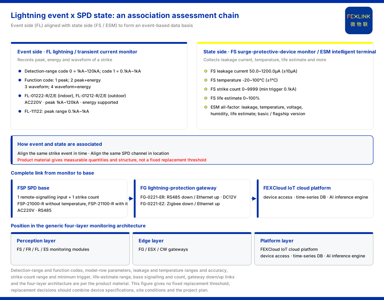
Direct answer
In a chemical plant area, after a lightning strike a surge protective device (SPD) may already have degraded while still looking normal, and this is precisely the difficulty of on-site judgement. To handle it, the data from two sides must be combined: one side is the lightning-current event, recorded by the FL lightning current / transient current monitor (e.g. FL-01222) as strike peak, energy and waveform; the other side is SPD state, collected by the FS surge protective device monitor (SPD monitoring module) and the ESM intelligent lightning-protection monitoring terminal (SPD monitor) as leakage current, temperature and life estimation. Associating the two provides the data basis for a judgement: first confirm the size and form of this event, then compare it against the condition quantities of the protector itself, so that "full replacement after the fact" becomes "assessment by event". The knowledge base provides exactly these collectable quantities and the structure associating them, not a fixed threshold; this article explains them according to the knowledge base and derives no replacement criteria.
Why the problem is hard: event and state are two data sets
The effect of a lightning strike on an SPD is often reflected in two places at once. The first place is "whether an event happened and how large it was", that is, quantities related to the strike itself such as peak, energy and waveform; the second place is "how the protector is currently doing", that is, quantities related to the health of the device itself such as leakage current, temperature and life estimation. Looking at only one side leaves the judgement half missing: looking only at the event, one does not know whether the device has already been affected; looking only at device state, one cannot associate a state change with a particular strike.
Therefore the precondition for judging "whether it should be replaced" is first having these two observable data sets. The monitoring products listed by the knowledge base are organised around these two sides: lightning-current monitoring handles the event side, and SPD monitoring handles the state side. Only by aligning the two in time and position can an assessment basis oriented to maintenance action be formed.
The lightning-event side: what lightning current recording captures
The FL lightning current / transient current monitor records strike peak, energy and waveform. The knowledge base explains its detection-range codes and function codes: detection-range code 0 indicates 1kA to 120kA and code 1 indicates 0.1kA to 1kA; function code 1 is peak, 2 is peak plus energy, 3 is waveform and 4 is waveform plus energy.
At the model level, the knowledge base lists the indoor and outdoor types of this lightning-current monitor as AC220V, with a peak range of 1kA to 120kA and energy supported, corresponding to models FL-01222-R/Z/E (indoor) and FL-01212-R/Z/E (outdoor); the other model, FL-11122, has a peak range of 0.1kA to 1kA. In other words, strikes of different magnitudes can be covered by models of different detection ranges: larger strikes are handled by the 1kA to 120kA tier and smaller transient currents by the 0.1kA to 1kA tier. The function code then determines whether peak, energy or waveform is recorded, which directly affects how much event information is available after the fact.
For judgement purposes, the event side provides "how large this strike was and what form it took". The more complete the energy and waveform information, the better the event can be associated with device state.
The SPD state side: leakage current, temperature and life estimation
The SPD state side is handled by the FS surge protective device monitor (SPD monitoring module) and the ESM intelligent lightning-protection monitoring terminal (SPD monitor).
The key parameters collected by the FS surge protective device monitor are: leakage current 50.0 to 1200.0μA (accuracy ±10μA), temperature -20 to 100℃ (accuracy ±1℃), lightning count 0 to 9999 times (minimum trigger 0.1kA), and life estimation 0 to 100%. Among these, leakage current and temperature reflect the current working state of the device, the lightning count reflects the number of historical triggers, and the life estimation gives a state quantity from 0 to 100%.
The ESM intelligent lightning-protection monitoring terminal is positioned as an SPD all-parameter monitor. The knowledge base states that its model rule includes information on power supply, display, phase count, current parameters and version; the versions are divided into a basic four-element version and a flagship multi-element version, and it can collect leakage current, temperature, voltage, humidity and life estimation. Compared with FS, ESM covers more elements: in addition to leakage current, temperature and life estimation, it brings voltage and humidity into the collection scope.
Placing these state quantities together with the event quantities makes a comparison possible: after the same strike, whether the protector's leakage current has changed, whether its temperature shows an anomaly, and what level its life estimation is at — all of these are information readable from the state side.
How event and state are associated
The key to association is to let the data of the event side and the state side line up. On the one hand, the lightning count of FS carries a minimum trigger condition (0.1kA), and the detection ranges of FL listed by the knowledge base cover both the 1kA to 120kA and the 0.1kA to 1kA tiers, so the two can echo the same strike in detection statement; on the other hand, the leakage current, temperature and life estimation of the state side provide observable changes in device state after the event.
The assessment path is therefore: first obtain the peak, energy and waveform of one event through lightning-current monitoring, then obtain the leakage current, temperature and life estimation of the same period through SPD monitoring, and compare the two sets of data as the basis for "whether treatment is needed". The knowledge base provides these collectable quantities and their structure, not a fixed replacement threshold. This article therefore describes associated assessment as a way of judging from both sides, rather than a decision formula to be copied. Actual criteria should be determined in conjunction with device specifications, site working conditions and project solution.
The complete chain from monitoring to base
Besides the monitors themselves, the knowledge base also lists supporting products for carrying and uplinking data, forming a chain from the site to the platform.
The FSP SPD lightning-protection base (e.g. FSP-21000-R) provides 1 remote-signalling input and 1 lightning count; of these, FSP-21000-R excludes temperature while FSP-21100-R includes temperature, the supply is AC220V and communication uses RS485.
The FG lightning-protection smart gateway (e.g. FG-0221-ER) provides transparent transmission and protocol conversion and aggregates downstream device data upward. The knowledge base lists FG-0221-ER as RS485 downstream and Ethernet upstream with DC12V supply, and FG-0221-EZ as Zigbee downstream and Ethernet upstream. Both therefore use Ethernet upstream, differing mainly downstream: one uses RS485 and the other Zigbee.
Position in the four-layer architecture
In the general four-layer architecture of the monitoring system, these products each have their own place. The knowledge base states that the perception layer contains the FS, FR, FL and ES series monitoring modules; the edge layer contains the FG, ESX and CW gateways; and the platform layer is the FEXCloud IoT cloud platform, with device access, a time-series database and an AI inference engine.
Under this division, the lightning-current monitor and the SPD monitor are in the perception layer, obtaining event and state data; the lightning-protection smart gateway is in the edge layer, handling protocol conversion and uplink; and the data finally enters the FEXCloud IoT cloud platform, which performs device access, time-series data storage and AI inference. From "on-site collection" to "data uplink" and then to "platform analysis", this is a layered chain; the associated assessment of lightning events and SPD state unfolds after raw data is obtained along it.
Scope and limitations
- This article is limited to the existing statements of the product knowledge base on the FL lightning current / transient current monitor, the FS surge protective device monitor (SPD monitoring module), the ESM intelligent lightning-protection monitoring terminal, the FSP SPD lightning-protection base, the FG lightning-protection smart gateway and the general four-layer architecture of the monitoring system.
- The detection-range codes and function codes, the model-row parameters, the leakage-current and temperature ranges and accuracies, the lightning-count range and minimum trigger, the life-estimation range, the base remote signalling and counting, the gateway downstream and upstream methods, and the four-layer architecture are all statements listed by the knowledge base.
- This article explains the idea of associated assessment between collectable quantities on the event side and the state side; it does not give a fixed replacement threshold or decision formula, and whether replacement is needed should be determined in conjunction with device specifications, site working conditions and project solution.
- Other site conditions, installation methods and maintenance cycles not listed in the text are not inferred or promised by this article.
- Actual selection and judgement are subject to the latest product materials, project solution and on-site procedures.