 FEXLINK Research Institute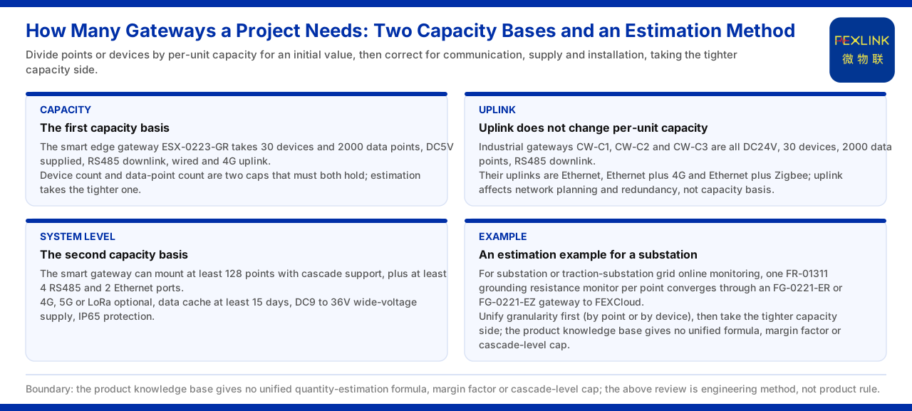
Direct Answer
How many gateways a project needs cannot be produced by a back-of-the-envelope formula; it first requires deciding which "capacity ruler" to use. The product knowledge base provides two comparable conventions. The first is the access capability of about 30 devices and 2000 data points per gateway. The second is that, in the system-level scheme, the smart gateway can mount not fewer than 128 monitoring points and supports cascading. The two conventions have different dimensions: the former counts by device and data point, the latter by monitoring point. The prudent engineering approach is to obtain an initial value by dividing the number of monitoring points or devices by the per-unit capacity, and then to revise it according to the communication method, the supply and installation conditions, and whether cascading is used. The product knowledge base gives no unified quantity-calculation formula, no margin factor and no upper limit on cascade levels, so any "standard algorithm" with a fixed coefficient lies outside the support of the product documents.
The First Capacity Convention: 30 Devices and 2000 Data Points per Unit
The smart edge-computing gateway table of the product knowledge base states that the intelligent edge-computing gateway (ESX-0223-GR) has an access capability of 30 devices and 2000 data points, uses a DC5V supply, with RS485 downward and wired plus 4G upward. This is the most direct per-unit capacity baseline. Under this convention, if a project needs to access 120 devices in total, then by device count alone about four units are needed; but if the total number of data points these devices produce approaches or exceeds the 2000-per-unit capacity, the data-point convention should be used to re-check. That is, device count and data-point count are two upper limits that must hold at the same time, and the tighter is taken.
The Upward Method Does Not Change the Per-Unit Capacity
The product knowledge base also states that the industrial gateway (CW-C1, CW-C2 and CW-C3) all have DC24V, 30 devices and 2000 data points, with RS485 downward and Ethernet, Ethernet plus 4G, and Ethernet plus Zigbee upward respectively. The three models differ in their upward method, but the per-unit access capacity is the same. The significance of this information is that choosing Ethernet, 4G or Zigbee solves the on-site backhaul condition and does not let a single gateway "hold more". When estimating quantity, therefore, the upward method mainly affects network planning and redundancy, not the capacity convention itself.
An Extended Gateway Still Uses the 30-Device Convention
In the product knowledge base, the industrial wearable controller (CX-08R06AI08-C1, CX-08R06AI08-C2 and CX-08R06AI08-C3) extends 8 digital channels and 8 analog channels beyond 30 devices and 2000 data points. This shows that for a gateway with IO expansion or a programmable device, the access-capacity convention is still based on 30 devices and 2000 data points; the extended IO channels are used for local acquisition and do not amount to raising the "accessible device count" as a whole.
The Second Capacity Convention: Not Fewer than 128 Points at System Level
The grounding resistance monitoring system reference parameters of the product knowledge base give another system-level convention: the smart gateway can mount not fewer than 128 points and supports cascading, and has not fewer than 4 RS485 channels and not fewer than 2 Ethernet channels, optional 4G, 5G or LoRa, a data cache of not fewer than 15 days, a DC9 to 36V wide-voltage supply, and a protection rating of IP65. This convention is closer to the scenario of "configuring by monitoring point", such as a project counted by the number of measurement points like online grounding-grid monitoring, and it faces a different granularity from the 30-device per-unit convention.
Handling of Cascading and Margin
Both conventions hint at the existence of cascading, but the product knowledge base gives neither the maximum number of cascade levels nor a margin factor. A reasonable estimation approach is therefore to calculate the theoretical number by the business convention first, then determine the lower limit by "taking the tighter side of the per-unit capacity"; whether to leave a margin and how much belong to engineering judgement and should not be written as a fixed product coefficient. If cascading is used on site, the conditions of supply, cabling and cache must be additionally confirmed, because parameters such as wide-voltage supply, cache days and protection rating describe capability boundaries.
An Estimation Example for a Substation Scenario
In its typical application scenarios and selection comparison, the product knowledge base gives the following recommended combination for "online grounding-grid monitoring of a substation or traction substation": one grounding resistance monitor (FR-01311) per monitoring point, aggregated through a lightning-protection smart gateway (FG-0221-ER or FG-0221-EZ), and then up to the FEXCloud IoT cloud platform. In this formulation, the number of gateways first depends on the total number of monitoring points: if the number of measurement points falls within the mounting capability of a single system-level unit, one gateway can cover it; if the measurement points increase markedly, they must be batched by the order of 128 points together with cascading. Note that this comparison gives a selection formulation, not a fixed configuration quantity for that scenario; the actual number of units is still subject to the concrete measurement-point list.
Whether to Count Monitoring Points or Devices First
When estimating the number of gateways, the first question to answer is not "how many units" but "by what granularity to count". If the project is measured in monitoring points, for example grounding-grid online monitoring deployed by grounding measurement point, then the system-level convention of "mounting not fewer than 128 points" is closer to reality; here the total number of measurement points should be counted first, and then how many points a single gateway can cover. If the project is measured in devices, for example connecting a batch of smart meters or monitoring terminals to the platform, then the convention of 30 devices and 2000 data points per unit is more direct. The two granularities make the same project yield different initial values. Unifying the granularity before estimation is therefore the first step in avoiding rework.
Revision for Supply and Installation Conditions
The capacity convention gives "how much can be connected", but whether the site can land it also depends on supply and installation. The product knowledge base shows that the intelligent edge-computing gateway (ESX-0223-GR) uses a DC5V supply, the industrial gateway uses DC24V, and the system-level scheme is described as DC9 to 36V wide voltage with IP65 protection. The inconsistency in supply voltage means that different models cannot be interchanged at will; wide voltage and a high protection rating point to harsher installation environments. If, during estimation, a site can only provide a 24V supply, its layout cannot be defaulted to the quantity of the 5V model.
Indirect Effect of the Communication Method on Quantity
The upward method does not change the per-unit capacity, but it indirectly affects the number of units. Taking Zigbee upward as an example, its networking characteristics determine that there is a constraint between coverage and node count; if the sites are scattered, local aggregation before upward transmission may be needed, changing the actual number of gateways deployed. The product knowledge base gives no node limit for Zigbee, so it cannot be used to calculate "how many devices one Zigbee gateway can carry at most". What engineering can do is: obtain the lower limit of the quantity by the capacity convention first, then revise it upward according to the communication coverage and the on-site topology, and confirm the feasibility of each aggregation point through survey.
Re-Checking the Estimation Result
After obtaining an initial value, a re-check from three directions is recommended. First, whether the total number of data points exceeds the 2000-point capacity of a single unit, avoiding a calculation based only on device count while ignoring data points. Second, whether the channels of the extended IO have been counted into the data points, avoiding treating expansion channels as "free capacity". Third, if cascading is used, whether the supply, cabling and cache conditions are satisfied, because cascading changes the dependence on a single unit's cache. Only after all three re-checks pass is the resulting number closer to an implementable scheme. The product knowledge base provides no unified estimation formula; the above belongs to engineering method, not a product rule.
Applicability and Limits
- The content of this article is limited to the product knowledge base's existing statements on gateway access capacity, upward method, expansion channels, system-level mounting parameters and scenario selection formulation, and does not extend to calculation formulas, margin factors or cascade-level upper limits not listed.
- The values in the text (30 devices, 2000 data points, not fewer than 128 points, not fewer than 4 RS485 channels, not fewer than 2 Ethernet channels, a cache of not fewer than 15 days, DC9 to 36V, IP65) are cited under the listed convention and do not constitute a configuration commitment for a specific project.
- The product knowledge base gives no unified quantity-estimation formula; the "calculate an initial value then revise" described here is an engineering recommendation that does not replace on-site survey and scheme design.