 FEXLINK Research Institute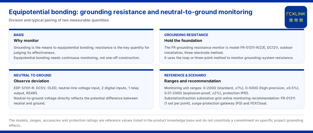
Direct Answer
The role of equipotential bonding in lightning protection can be summarised as keeping the conductive parts within a system at approximately the same potential, so that a lightning strike or fault current does not seek another path through a potential difference. The product knowledge base gives landing points from two monitorable quantities: first, the resistance of the grounding system, monitored by the FR grounding resistance monitor (for example FR-01311-R); and second, the neutral-to-ground voltage, monitored by the ESP neutral-to-ground voltage monitor (for example ESP-12101-R). The former reflects whether the "foundation" of equipotential bonding is reliable, and the latter reflects whether the equipotential has shifted. Bringing these two classes of data into monitoring moves the condition of equipotential bonding from "whether it was done" to "whether it remains effective".
1. Why Equipotential Bonding Is the Basis of Lightning Protection
One core of lightning protection is to give the lightning current a controllable discharge path and to keep the potential difference among the parts within the system as small as possible. The product knowledge base records that the grounding resistance monitor is used to monitor the resistance of the grounding system and thereby safeguard the basis of equipotential bonding. This sentence points out the relation between grounding and equipotential: grounding is the means of realising equipotential, and resistance is the key quantity for judging whether it is effective.
If the resistance of the grounding system deviates from expectation, the "foundation" of equipotential bonding is unstable and the potential distribution along the lightning-current discharge path changes accordingly. Equipotential bonding is therefore not a one-off construction but an object requiring continuous monitoring. The product knowledge base lists grounding resistance monitoring as an independent product line precisely because this condition quantity needs long-term, quantifiable observation.
2. Grounding Resistance Monitoring Safeguards the Foundation of Equipotential Bonding
On the grounding side, the product knowledge base records that the FR grounding resistance monitor uses the loop method or the three-point method, with models FR-01311-R and FR-01311-Z and FR-01311-E (twelve volts DC, outdoor installation, three-pole method), to monitor the resistance of the grounding system. The three-pole method and the loop method are different measurement methods corresponding to different site conditions; outdoor installation shows that it faces scenarios such as outdoor grounding grids.
The first step in choosing grounding resistance monitoring is to confirm that the measurement method matches the site conditions. A grounding grid is an outdoor facility, and the grounding electrodes, down-conductors and soil conditions together determine the resistance, so the monitor needs to work outdoors over the long term. The product knowledge base marks this model as outdoor installation and three-pole method precisely to match such scenarios. Once the measurement method is fixed, grounding resistance monitoring has a comparable reading basis.
3. Neutral-to-Ground Voltage Monitoring Observes the Shift of the Equipotential
Whether the equipotential has shifted can be seen not only from the grounding resistance but also from the neutral-to-ground voltage. The product knowledge base records that the ESP neutral-to-ground voltage monitor has the model ESP-12101-R, with a five-volt DC supply, an OLED display, a "neutral-line input" voltage, two digital inputs, one relay output and RS485 communication, used to monitor the neutral-to-ground voltage, the key quantity that characterises the equipotential state.
The neutral-to-ground voltage can characterise the equipotential state because it directly reflects the potential difference between the neutral line and the ground. In a normal equipotential state this difference should be at a low level; once the grounding or equipotential bonding becomes abnormal, the difference may rise. The product knowledge base also gives digital inputs and a relay output, showing that the monitor can not only read voltage but also accept status quantities and output control signals for linkage with other devices.
4. System-Level Reference Parameters and Protection Rating
At the system level, the product knowledge base gives reference parameters for grounding resistance monitoring: a monitoring-unit range of 0 to 200 ohms (standard type, plus or minus 1 percent), 0 to 500 ohms (high-accuracy type, plus or minus 0.5 percent) and 0.01 to 200 ohms (explosion-proof type, plus or minus 2 percent), with a protection rating of IP65. These parameters provide a comparison for range and accuracy selection in different scenarios.
Range and accuracy should be read together. The standard type covers 0 to 200 ohms, the high-accuracy type extends to 0 to 500 ohms, and the explosion-proof type covers the smaller resistance interval of 0.01 to 200 ohms. Different accuracies correspond to different grades, and selection should be determined by the range and accuracy required on site rather than by a single number. The IP65 protection rating responds to the need for outdoor installation and shows that the system-level monitoring unit can work in an outdoor environment. The explosion-proof grounding resistance monitor (FRP) faces locations requiring explosion protection and contrasts with the standard type.
5. Through-Connection from the Perception Layer to the Platform
The data of equipotential monitoring has to enter a unified system. The product knowledge base records that the perception layer of the general four-layer architecture of the monitoring system contains the FS, FR, FL and ES series monitoring modules, and the grounding (FR) and neutral-to-ground voltage (ESP) data are aggregated into the system from there. That is, grounding and neutral-to-ground voltage are not two isolated readings but acquisition contents of the same perception layer.
This path shows that equipotential monitoring can share one architecture with other monitoring such as lightning protection and electrical safety. The grounding resistance and neutral-to-ground voltage are acquired at the perception layer and transmitted upward, and can later be summarised in the same system. For sites that need to observe several classes of electrical quantity at once, this through-connection reduces the duplicated investment of building separate systems and allows the equipotential state to be judged together with other data.
From the division of data, the grounding resistance answers "whether the grounding system itself is reliable", while the neutral-to-ground voltage answers "whether the equipotential has shifted"; the two complement each other. Monitoring only one of them may fail to show the whole equipotential state: with normal grounding resistance, the neutral-to-ground voltage may still shift because of wiring or load, and a stable neutral-to-ground voltage cannot replace long-term observation of the grounding resistance. Only by placing both classes of data in the same architecture can one judge more completely whether equipotential bonding remains effective.
6. Basis and Typical Scenarios
Behind the monitoring requirement of equipotential bonding there is a clear safety basis. The product knowledge base records that an abnormal open circuit of the grounding resistance is listed as a safety red line, based on GB 50057. Setting "abnormal open circuit of the grounding resistance" as a red line on its own shows that the failure of equipotential bonding is regarded as a risk that must be intercepted with priority.
In typical scenarios, the product knowledge base gives a recommended combination for "online monitoring of substation and traction-substation grounding grids": the grounding resistance monitor FR-01311 (one set per point), the lightning-protection smart gateway (FG) and the FEXCloud IoT cloud platform. This combination covers the complete link from field measurement and data aggregation to platform presentation. The product knowledge base also records that the FR and FRP series grounding resistance monitors have been applied to online monitoring of railway traction-substation grounding grids and to the Jinzhou Port oil-tank farm (10 sets per tank), showing that equipotential and grounding monitoring already has engineering landing.
Applicability and Limits
First, this article states only the relation between equipotential bonding and grounding resistance and neutral-to-ground voltage monitoring, and its factual boundary is the product knowledge base; it introduces no standard clause, parameter, certification or case not listed in the product knowledge base.
Second, the models FR-01311-R and FR-01311-Z and FR-01311-E of the FR grounding resistance monitor and its three-pole method, the model ESP-12101-R of the ESP neutral-to-ground voltage monitor and its interface configuration, the system-level reference ranges and the IP65 protection rating, and the GB 50057 basis and typical application combination are all contents listed in the product knowledge base.
Third, the ranges, accuracies and protection rating referred to in this article are the reference values listed in the product knowledge base and do not constitute a promise about the grounding effect of a specific project; scheme selection follows the site conditions and the product knowledge base conventions.