 FEXLINK Research Institute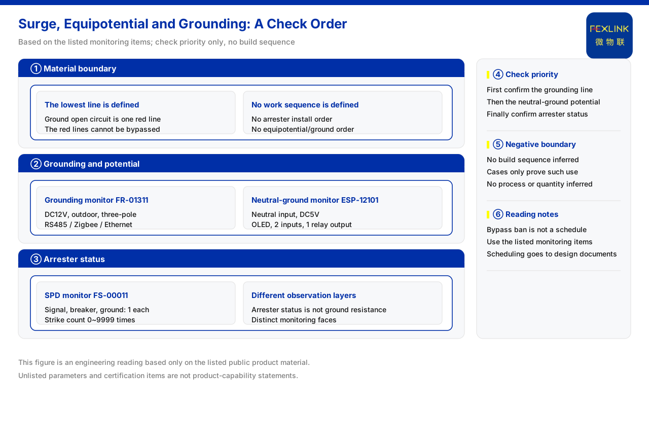
Direct answer
Regarding the order of lightning-protection device work, equipotential bonding, and grounding retrofit, the current product documentation does not specify a construction sequence, so no authoritative construction ordering can be read directly from the documentation. What can be confirmed is another kind of order: the documentation lists "abnormal open circuit of grounding resistance" as one of the non-bypassable red lines, there being five red lines that cannot be bypassed and whose threshold no one can raise; it also treats the grounding resistance monitor and the neutral-to-ground voltage monitor as basic monitoring items for grounding and potential state, and uses the surge protective device monitor to monitor the device's own remote signalling, switch, grounding, and lightning-count state. On this basis what can be determined is a verification priority: first confirm whether the baseline of grounding and potential is monitored, then confirm whether the device state is monitored; but the documentation does not thereby give a construction schedule of which trade comes first.
What the documentation defines is a baseline, not a work sequence
The two things most easily confused in engineering practice are the safety baseline and the construction schedule. The current product documentation has an explicit rule for the former: abnormal open circuit of grounding resistance is listed as a red line, based on the building lightning-protection design code; the group of red lines numbers five and is described as non-bypassable, with no one able to raise the threshold. "Non-bypassable" means that this baseline cannot be switched off or have its threshold raised in the monitoring and alarm logic, not that it prescribes whether to lay the grounding grid first or install the protective device first. The documentation has no rule for the latter: its full text gives no sequence among lightning-protection device installation, equipotential bonding, and grounding retrofit. Only by making this clear can "the baseline is non-bypassable" be prevented from being misread as "grounding must be done first".
Grounding-resistance monitoring as baseline observation of grounding state
Since the baseline is an abnormal open circuit of grounding resistance, observing grounding resistance is the basic means of judging whether the baseline is held. The current product documentation lists the grounding resistance monitor (FR-01311-R, FR-01311-Z, FR-01311-E), which uses a DC12V supply, outdoor installation, and the three-electrode method, with communication as RS485, Zigbee, and Ethernet respectively, an aluminium housing, and dimensions of 204×202×72mm. The three-electrode method means it measures the resistance state of the grounding body by arranging electrodes, which is direct observation of grounding performance rather than indirect inference. The documentation places this class of equipment in the grounding and potential category, showing that at the monitoring level the grounding state is itself an object that needs separate, continuous observation.
Neutral-to-ground voltage monitoring supplements potential-state observation
Beyond grounding, the potential difference is also part of the baseline. The neutral-to-ground voltage monitor (ESP-12101-R) given by the current product documentation uses a neutral-line input, has a DC5V supply, carries OLED display, provides two switching-quantity inputs and one relay output, and communicates over RS485. It observes the potential difference between the neutral line and ground, an indicator that complements the grounding state: an abnormal open circuit of grounding resistance is listed as a red line, while the neutral-to-ground voltage reflects whether the potential relationship is normal. The documentation places the neutral-to-ground voltage monitor and the grounding resistance monitor together in the digital electricity-use and electrical-safety monitoring product line, showing that the two play mutually supporting basic roles in grounding and potential monitoring.
SPD status monitoring belongs to another observation layer
Beyond grounding and potential, the health state of the protective device itself also needs to be observed. The surge protective device monitor (FS-00011-R) listed by the current product documentation uses a DC12V supply, with one channel each of remote signalling, switch status, grounding status, and lightning count, and RS485 communication; among its key parameters, the lightning count is 0 to 9999 with a minimum trigger of 0.1kA. These monitoring items show that the surge protective device monitor is concerned with whether the protective device has been triggered, whether the switch and grounding states are normal, and whether the lightning count has accumulated, rather than the resistance value of the grounding body. It therefore belongs to state observation at the protective-device level, at a different observation layer from grounding-resistance monitoring and neutral-to-ground voltage monitoring.
What the listed application cases establish
The current product documentation mentions in a note on the grounding resistance monitor that this class of equipment has been applied to online monitoring of the grounding grid of a railway traction substation, and to the Jinzhou Port tank-farm project, where the tank farm uses 10 sets per tank. What this information can confirm is the application target and the configuration quantity, that is, that the equipment has deployment records in strong-current and petrochemical settings sensitive to grounding and potential. It cannot be used to infer a construction sequence: the documentation states only where it is used and how much, not whether grounding retrofit comes before or after installing monitoring equipment. Limiting the role of the case to "proving that such applications exist" avoids deriving a process conclusion from the case.
Rewriting the ordering question as a verification sequence
Since the documentation does not specify a construction schedule, a workable approach is to rewrite "order" as "verification priority". First, confirm whether the grounding-resistance baseline is already continuously monitored, because an abnormal open circuit of grounding resistance is a non-bypassable red line. Second, confirm whether the neutral-to-ground voltage, a potential indicator, is already observed, to supplement the potential judgment beyond grounding. Third, confirm whether the remote signalling, switch, grounding, and lightning-count states of the surge protective device are already monitored, to cover the health of the protective device itself. Fourth, check whether there is a requirement to arrange grounding retrofit, equipotential bonding, and protective-device installation into a fixed sequence; if so, it should be clearly marked as a matter the current documentation does not list, to be handled by the engineering design documents and codes. This check yields "which baselines must be monitored first", not "which trade must be constructed first".
Scope and limitations
First, this article restates only what the current product documentation lists, with the factual boundary limited to the abnormal-open-circuit red line and its basis, the number of red lines and the non-bypassable attribute, the model and configuration of the grounding resistance monitor, the model and configuration of the neutral-to-ground voltage monitor, the monitoring items and key parameters of the surge protective device monitor, the listed application cases, and the documentation not specifying a construction sequence.
Second, the construction sequence of lightning-protection device installation, equipotential bonding, and grounding retrofit is content the documentation does not list, and this article makes no process inference.
Third, the three-electrode method, supply, and communication of the grounding resistance monitor are cited as listed; this article does not conclude on its measurement accuracy, applicable soil conditions, or installation details.
Fourth, the display, inputs and outputs, and communication of the neutral-to-ground voltage monitor are cited as listed; this article does not judge the acceptable range of the neutral-to-ground voltage.
Fifth, the lightning count range and minimum trigger of the surge protective device monitor are cited as listed; this article does not infer a conclusion about its coordination with the protective device's withstand.
Sixth, the listed application cases serve only to state the application target and configuration and do not commit to a construction sequence or on-site result; the latest product documentation and project scheme govern in practice.