 FEXLINK Research Institute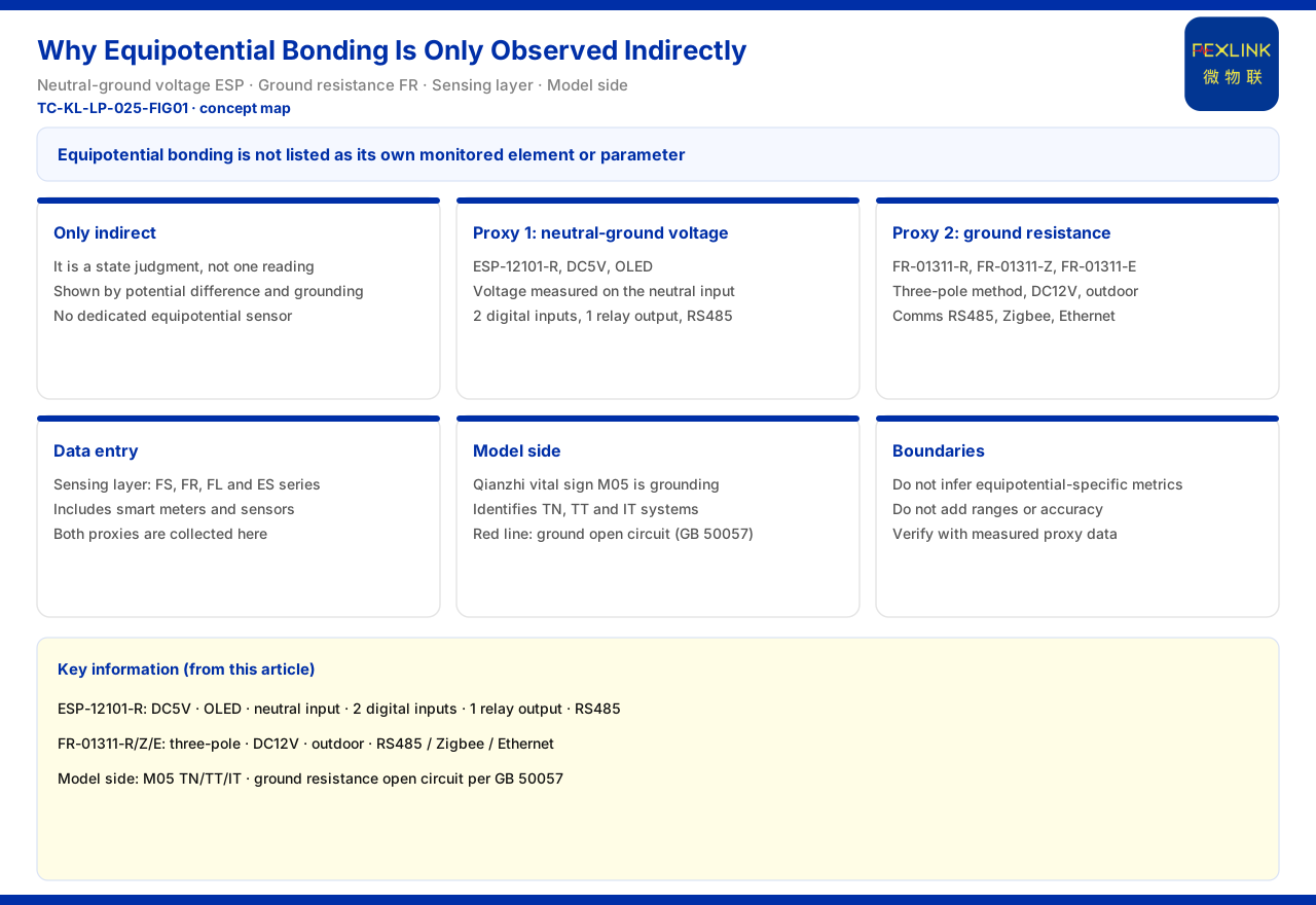
Direct Answer
Equipotential bonding is not listed in the product knowledge base as an independent monitoring element or product parameter; it can be observed only indirectly, through proxy quantities. The two main proxy quantities given by the product knowledge base are neutral-to-ground voltage and grounding resistance. Neutral-to-ground voltage is monitored by the neutral-to-ground voltage monitor (ESP-12101-R), supplied at DC5V, with an OLED display, a voltage measurement object of "neutral input", 2 digital inputs, 1 relay output and RS485 communication. Grounding resistance is monitored by the grounding resistance monitor (FR-01311-R, FR-01311-Z and FR-01311-E), which uses the three-pole method, is supplied at DC12V and is installed outdoors. Both are collected at the perception layer of the general four-layer architecture of the monitoring system and flow into the platform together with the other modules. On the model side, grounding is treated as a basic vital sign, and M05 identifies the three grounding systems TN, TT and IT; "grounding resistance abnormal open circuit" is listed as a safety red line, based on GB 50057. It should be noted that the product knowledge base does not list equipotential bonding separately, so this article cites only the proxy quantities and does not infer a dedicated monitoring index or threshold for equipotential bonding.
1. Why Equipotential Bonding Can Only Be Observed Indirectly
Equipotential bonding describes a state in which the potentials of the various parts within a system are close to equal. It is not itself a single quantity that can be read out directly; it is expressed jointly by potential difference and grounding state. The treatment in the product knowledge base is consistent with this: it does not list a monitoring item named equipotential bonding, but gives two measurable proxy quantities, one being the voltage between neutral and ground, the other being the resistance of the grounding body. The former reflects whether the potential has shifted, and the latter reflects whether the reference ground of the potential is reliable. Only by understanding this indirect relationship can the product parameters that follow be read correctly, without wrongly assuming that there is a dedicated sensor called equipotential bonding. In other words, equipotential bonding is a state judgment supported by several measurable quantities, not a reading from a single instrument; this also means that, when reading, both neutral-to-ground voltage and grounding resistance should be watched.
2. Proxy Quantity One: Neutral-to-Ground Voltage
The product knowledge base records that the neutral-to-ground voltage monitor (ESP-12101-R) is supplied at DC5V, shows on an OLED display, measures the neutral input as its voltage object, has 2 digital inputs, 1 relay output and RS485 communication, and is used to monitor neutral-to-ground voltage, a key quantity that characterizes the equipotential state. Neutral-to-ground voltage directly reflects the potential difference between neutral and ground; in a normal state this difference should stay at a low level, and once grounding or a connection becomes abnormal the difference may rise. The product knowledge base also gives digital inputs and a relay output, showing that the monitor can not only read voltage but also take in status quantities and output a control signal. This article cites only the above interfaces and parameter figures and does not add ranges or thresholds not listed in the product knowledge base.
3. Proxy Quantity Two: Grounding Resistance
The other proxy quantity is grounding resistance. The product knowledge base records that the grounding resistance monitor (FR-01311-R, FR-01311-Z and FR-01311-E) uses the three-pole method, is supplied at DC12V, is installed outdoors, and communicates over RS485, Zigbee and Ethernet respectively, and is used to monitor the resistance of the grounding grid, since grounding state is a foundation quantity for protection. Grounding resistance answers whether the grounding system itself is reliable; it is the reference that allows equipotential bonding to hold. The product knowledge base does not give the resistance range or accuracy of this instrument, so this article cites only the measurement method and installation mode and does not add range values.
4. Data Entry: Collection at the Perception Layer
The product knowledge base records that the perception layer of the general four-layer architecture of the monitoring system includes the FS, FR, FL and ES series monitoring modules, as well as smart meters and sensors, where the sensors include Rogowski coils, thermistors and microampere-level leakage-current sensors. The neutral-to-ground voltage and grounding data are collected exactly at this layer, forming the data entry through which equipotential bonding becomes observable. This shows that equipotential observation is not deployed in isolation but shares the same perception architecture with lightning protection, electrical safety and other monitoring. After collection at the perception layer, the data is passed upward and can be aggregated in the same system, making it convenient to judge the two proxy quantities together.
5. Model Side: Grounding as a Base Quantity and a Safety Red Line
On the model side, the product knowledge base gives two records related to grounding. First, the Qianzhi engine basic vital sign M05 is grounding, used to identify the three grounding systems TN, TT and IT, which treats grounding-system identification as parameter-level perception and shows that grounding and the equipotential state are treated as a base quantity in the system. Second, in the safety red-line guard, "grounding resistance abnormal open circuit" is based on GB 50057, and no one can raise the threshold, which shows that the failure of this equipotential foundation is treated as unacceptable by the standard. The product knowledge base also records that the Wanxiang engine includes topology-cascade impact analysis, traceable through up to 6 layers, and has cross-dimension association rules, among which CURR-014 is "zero-sequence current sustained to single-phase grounding traceability", showing that grounding-type anomalies can be traced upward along the topology. This article cites only these mechanisms, does not repeat specific trigger values, and does not infer a dedicated threshold for equipotential bonding.
6. Boundaries That Must Be Held
The above can be gathered into a reading order. The first step is to confirm that equipotential bonding has no independent monitoring item and can only be observed through proxy quantities. The second step is to read neutral-to-ground voltage and cite the supply, display, input and output of ESP-12101-R. The third step is to read grounding resistance and cite the FR grounding resistance monitor model FR-01311-R, FR-01311-Z and FR-01311-E, together with their measurement method and installation mode. The fourth step is to confirm that the data entry is at the perception layer. The fifth step, if the model side is involved, is to cite M05 grounding-system identification, the grounding-resistance abnormal open circuit in the safety red lines, and the topology-cascade and association-rule framework. The boundary that must be held is that the product knowledge base does not list equipotential bonding as an independent element or product parameter, and this article does not infer a dedicated monitoring index or threshold for it; actual interpretation must be verified separately against the measured data of the proxy quantities.
Scope and Limitations
First, this article restates only the content listed in the product knowledge base, and its factual boundary is limited to the records of the neutral-to-ground voltage monitor, the grounding resistance monitor, the four-layer architecture and the Qianzhi and Wanxiang engines, without introducing indices or cases not listed in the product knowledge base.
Second, the DC5V supply, OLED display, neutral input, 2 digital inputs, 1 relay output and RS485 of the neutral-to-ground voltage monitor (ESP-12101-R) are quoted according to the figures listed in the product knowledge base; this article adds no range or threshold.
Third, the three-pole method, DC12V supply, outdoor installation and three communication options of the FR grounding resistance monitor (FR-01311-R, FR-01311-Z, FR-01311-E) are quoted according to the figures listed in the product knowledge base; this article adds no resistance range or accuracy.
Fourth, the composition of the perception-layer modules and sensors, the M05 grounding-system identification, the grounding-resistance abnormal open circuit in the safety red lines and its GB 50057 basis, and the topology-cascade and association-rule framework are all quoted according to the figures listed in the product knowledge base; this article does not repeat specific trigger values.
Fifth, the product knowledge base does not list equipotential bonding as an independent monitoring element, and this article accordingly states that it is observed indirectly only through the two proxy quantities of neutral-to-ground voltage and grounding resistance.
Sixth, this article does not constitute a commitment about diagnosis or system integration for any specific project; actual practice is subject to the latest product materials and formal documents.