 微物联研究院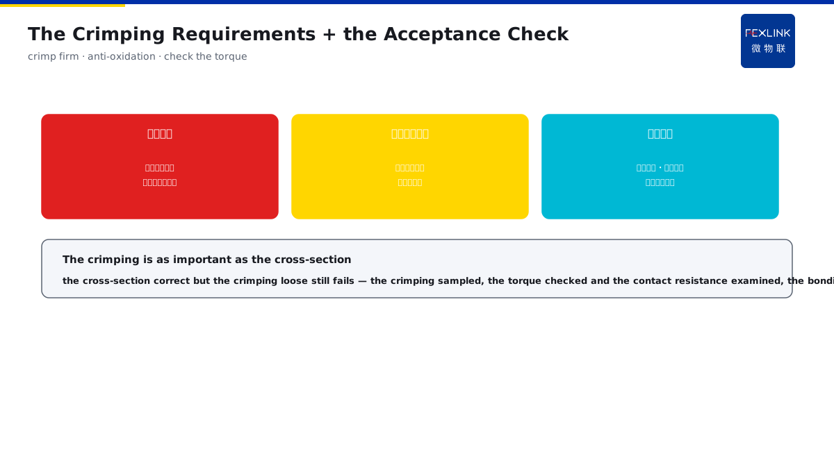
Direct Answer
During the construction, how thick a copper conductor should the equipotential bonding line use, and how should the several sizes on the drawing be selected? The answer: the cross-section of the equipotential bonding conductor is determined by the cross-section of the main conductor it connects and the protection class — the main equipotential bonding (MEB) line is generally not less than half of the incoming PE cross-section (commonly 16-25 mm² copper), and the local and supplementary bonding lines can be selected at 6-16 mm²; the key is to meet the minimum thermal-stable cross-section that "does not break and maintains the equipotential under the expected fault and the lightning current", rather than the thicker, the better.
At a workshop, when the main equipotential bonding was done, the construction used 25 mm² copper lines everywhere by experience, while the incoming PE was only 25 mm²; the supervisor pointed out that the MEB line only needed not less than half of the PE, so 25 mm² was a waste; at the local bonding points, 6 mm² was used everywhere, and some terminals were not crimped firmly, so the acceptance failed. After the re-selection by "the main half-value + the segmented grading": the MEB 16 mm², the local bonding 10 mm², and the supplementary bonding 6 mm², the acceptance passed after the crimping was qualified. The key distinction: the cross-section is not by experience — the MEB line is not less than half of the incoming PE cross-section (commonly 16-25 mm²), and the local and supplementary lines are graded at 6-16 mm²; the key is to meet the thermal stability without breaking, rather than the thicker, the better.
Why:
- The MEB: not less than half of the PE;
- The local/supplementary: graded at 6-16 mm²;
- The thermal stability: not breaking under the fault and the lightning current;
- The crimping quality: the terminal crimping must be reliable.
Key insight: "The cross-section is graded by the main half-value — the MEB line is not less than half of the incoming PE (16-25 mm²), and the local and supplementary lines are graded at 6-16 mm²; the key is the thermal stability without breaking and maintaining the equipotential, and the crimping quality is as important as the cross-section."
At a commercial building, during the completion acceptance, the equipotential bonding lines were all selected at the maximum cross-section, increasing the cost and making the terminal crimping difficult; after the re-selection by "the main half-value + the grading", the cost decreased and the acceptance passed at once. Lesson: the cross-section is not the thicker, the better — grade it by the PE half-value and the protection class, and the thermal stability being met is enough; the over-selection is a waste.
Overview: run "how to select the MEB/LEB/supplementary lines → how to derive the main half-value → where the copper-bar and the copper-wire differences lie → what the crimping requirements are" as one bonding-line selection cognition. The cross-section of the equipotential bonding conductor is determined by the cross-section of the main conductor it connects and the protection class; the MEB line is generally not less than half of the incoming PE cross-section (commonly 16-25 mm² copper), and the local and supplementary bonding lines can be selected at 6-16 mm². The four layers are unfolded below.
A "bridge-pier bearing" analogy: think of the bonding-line selection as reinforcing the bridge piers. The force (the fault/lightning current) the pier (the bonding line) must bear depends on the load of the bridge deck (the main conductor) — a heavy deck needs a thicker pier; a light deck needs only a thinner one. The "not less than half of the PE" in the standard is "the pier is at least configured for the half load of the deck", and the thermal stability is the bottom line of "the pier not being washed away"; the copper bar and the copper wire are the "material and the process of the pier" — the big pier cast in place (the copper bar) and the small pier built with bricks (the copper wire). The key is not the thicker the pier, the better, but the force matched and not washed away. The pier analogy: the bonding line = the pier, the main conductor = the deck, and the pier is configured for the half load of the deck (the PE half-value); the thermal stability = the bottom line of not being washed away, and the copper bar/wire = the big pier cast / the small pier built with bricks, with the force matched.
1. The Three Graded Cross-Sections: How to Select MEB/LEB/Supplementary
Step one: first look at how to select the three grades of the MEB, the LEB and the supplementary lines.
The MEB line:
- Connecting all the conductive parts at the incoming point;
- Not less than half of the PE cross-section;
- Commonly 16-25 mm² copper;
- The whole-building reference.
The LEB line:
- Connecting the equipment and the metal in the local area;
- Selected at 6-16 mm²;
- Combined with the branch cross-section;
- The regional reference.
The supplementary bonding line:
- Connecting between two devices/terminals;
- Starting at 6 mm²;
- Meeting the thermal stability;
- The point bonding.
Key insight: "The three grades are selected separately — the MEB not less than half of the PE (16-25 mm²), the LEB at 6-16 mm², and the supplementary starting at 6 mm²; grade by the bonding scope and the main cross-section connected, not one unified specification."
2. The Half-Value Principle: How to Derive It
Step two: the principle of deriving the cross-section from the half value of the main conductor.
The half-value logic:
- The bonding line serving the main conductor;
- The cross-section taking the half of the main;
- The thermal stability sufficient;
- Avoiding the over-waste.
The PE cross-section basis:
- The incoming PE cross-section known;
- The bonding line taking the half by reference;
- Combined with the protection class;
- The final cross-section determined.
The exceptions:
- The lightning-current path strengthened;
- The long distance corrected;
- The special places enlarged;
- Checked per the standard.
Key insight: "The half-value principle is derived — the bonding line serves the main conductor and taking the half of the main cross-section is thermally sufficient; take the half based on the incoming PE and combine the protection class, and the lightning-current path and the special places are enlarged and checked per the standard."
3. The Copper Bar vs the Copper Wire: Where the Differences Lie
Step three: the mechanical and current-carrying differences between the copper bar and the copper wire.
The copper-bar characteristics:
- The high mechanical strength;
- The good heat dissipation and the large current-carrying;
- The large connection surface and the good crimping;
- Used for the main conductor and the MEB.
The copper-wire characteristics:
- The soft and easy laying;
- The flexible bending;
- The convenient terminal crimping;
- Used for the branches and the supplementary.
The selection principle:
- The main conductor preferring the copper bar;
- The branches using the copper wire;
- The mechanical strength matched;
- The current-carrying and the thermal stability met.
Key insight: "The copper bar and the copper wire differ — the copper bar has the high mechanical strength and the good heat dissipation with the large current-carrying, used for the main conductor and the MEB; the copper wire is soft and easy to lay, used for the branches and the supplementary; select by matching the mechanical strength and meeting the current-carrying and the thermal stability."
4. The Crimping Requirements: How to Crimp the Terminal Board
Step four: the crimping requirements of the bonding line and the terminal board.
The crimping quality:
- The terminal crimping must be firm;
- The contact surface cleaned;
- The anti-oxidation and the anti-loosening;
- The crimping tool matched.
The terminal-board requirements:
- The material matched with the conductor;
- The connection points reliable;
- The quantity sufficient;
- The marking clear.
The acceptance check:
- The crimping sampled;
- The torque checked;
- The contact resistance checked;
- The bonding firm.
Key insight: "The crimping requirements are strict — the terminal crimping must be firm, the contact surface cleaned, and the anti-oxidation and the anti-loosening ensured; the terminal-board material is matched and the connection reliable; the acceptance samples the crimping, checks the torque and examines the contact resistance."
5. Product Implementation: The Bonding Effect Verifiable
WeiWuLian products bring the equipotential-bonding effect to the verifiable level:
- ESP neutral-ground-voltage monitor: the online monitoring of the equipotential effect;
- The trend warning: the early identification of the bonding degradation;
- The strike review: the bonding effect compared with the events;
- The loop improvement: the bonding maintenance backed by the data.
The design principle in one sentence: "The cross-section selected correctly and the effect measured accurately — the bonding line is graded by the half-value, and the ESP monitors the neutral-ground voltage online to verify the equipotential effect, so the bonding degradation is found early and the maintenance is backed by the data."
6. Common Understanding Misjudgments
- "The thicker the bonding line, the better": wrong. The half-value grading with the thermal stability met is enough, and the over-selection is a waste.
- "One unified specification everywhere": wrong. The MEB/LEB/supplementary are graded separately.
- "Only the cross-section, not the crimping": wrong. The crimping quality is as important as the cross-section.
- "No difference between the copper wire and the bar": wrong. The mechanical strength and the current-carrying differences decide the positions.
- "Done after the installation": wrong. The bonding may degrade and must be monitored and verified.
Scope and Limitations
This article explains the cross-section selection of the equipotential bonding lines (the three graded cross-sections, the half-value principle, the copper-bar/wire differences, and the crimping requirements), applicable to the bonding-line design and the construction acceptance. The specific cross-section values follow GB 50057-2010, GB 51348-2019 and the drawing sets; this article explains only the selection logic. All cases are anonymized (a workshop/a commercial building) and do not refer to any specific customer.