 微物联研究院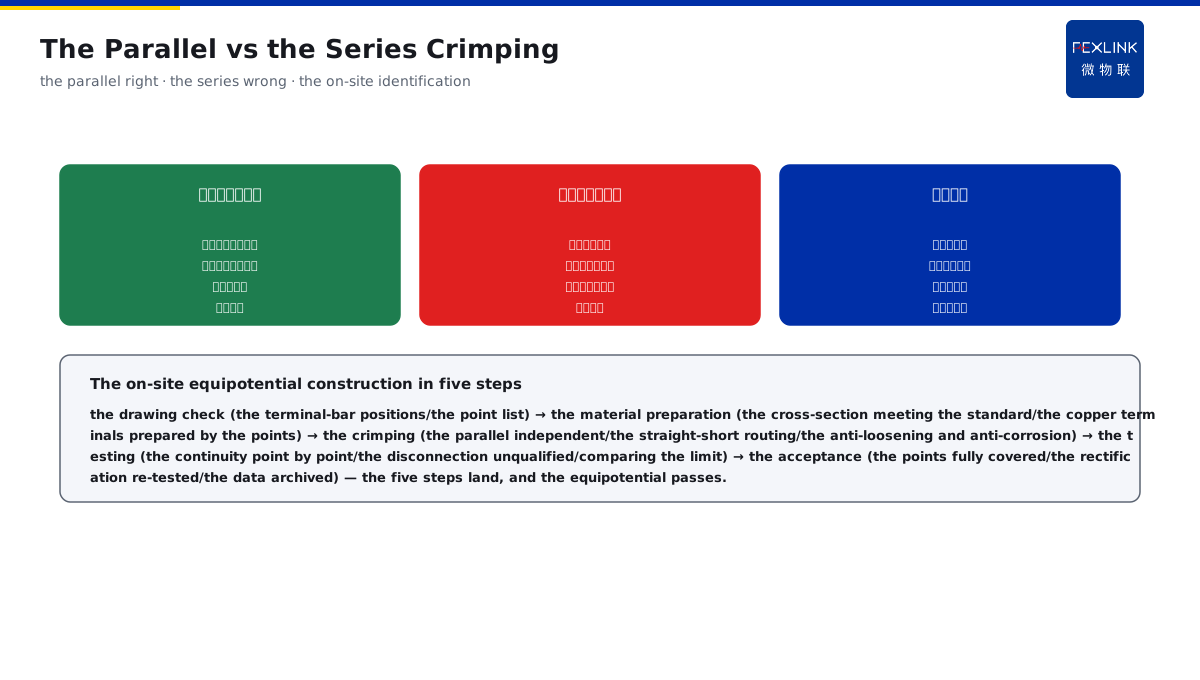
Direct Answer
When the drawings show the equipotential terminal bars, how should the site actually wire them to pass? The answer: the construction points are that the MEB terminal bar is installed beside the incoming-line main distribution cabinet, and the PE main pipes, the water-supply and drainage, the HVAC and the building metal structures are pressed and connected in parallel nearby with the shortest conductors (series connection prohibited); the LEB draws another loop locally in the bathrooms, the computer rooms and the explosive-hazard areas; the bonding conductors should be straight and short, with the cross-section meeting the standard, pressed with the copper terminals and treated with the anti-loosening and the anti-corrosion, and the acceptance tests the continuity point by point.
At an operating-room retrofit project of a hospital, the construction team connected the operating-room metal door, the equipment shells and the water pipes in series with one conductor to the LEB terminal bar, and the acceptance continuity test found the middle point disconnected with the end equipment losing the equipotential; after redoing with the parallel individual crimping, the point-by-point continuity passed. The construction core: the MEB beside the main cabinet with the parallel crimping, the LEB drawing another loop locally, and the conductors straight and short with the cross-section meeting the standard — parallel not series, and the continuity tested point by point.
Why:
- The MEB position: beside the incoming-line main distribution cabinet;
- The parallel crimping: series prohibited, the shortest nearby conductors;
- The LEB local: drawing another loop in the bathrooms/computer rooms/explosive-hazard areas;
- The acceptance continuity: tested point by point, with the anti-loosening and the anti-corrosion.
Key insight: "The construction has four points — the MEB beside the main cabinet (the nearby parallel crimping), the LEB local loop (the bathrooms/computer rooms/explosive-hazard areas), the bonding conductors straight and short (the cross-section meeting the standard/the copper-terminal crimping/the anti-loosening and the anti-corrosion), and the acceptance testing the continuity point by point (the disconnection means unqualified) — parallel not series, and the earthing reliable."
At an office-building decoration project, the equipotential bonding conductor was routed around with a long path and a small cross-section, and the acceptance continuity test passed but the resistance was large; after changing to the shortest straight routing and increasing the cross-section per the requirement, the test value returned to normal. Lesson: the bonding conductor "straight and short with the cross-section meeting the standard" is not a suggestion but a requirement — the long routing and the thin conductor make the equipotential exist in name only.
Overview: run "how the MEB/LEB terminal bars are installed → the parallel vs the series crimping → the bonding conductor shortest straight routing → the continuity test and the acceptance" as one equipotential-bonding construction field guide. The construction points: the MEB terminal bar is installed beside the incoming-line main distribution cabinet, and the nearby parallel crimping; the LEB draws another loop locally. The four layers are unfolded below.
A "corridor distribution box and the household wiring" analogy: think of the MEB terminal bar as the corridor master distribution box, with each household's wires independently connected from its own home to the master box (in parallel): if one household changes its wiring or loses power, the other households are unaffected; if the household wires are strung into one conductor in the corridor before entering the master box (in series), when the connector of a middle household loosens, all the households behind lose power. The equipotential bonding works the same: the PE main pipes, the water-supply and drainage pipes, the HVAC ducts and the building metal structures each have their bonding conductor independently pressed to the MEB terminal bar, and any branch inspection or disconnection does not affect the other branches; once a single conductor is strung to the end, when any middle crimping point loosens or corrodes, all the equipment behind loses the equipotential protection, and this hazard hides in the wall and is not easy to find in the acceptance. The LEB terminal bar is like the weak-current box on each floor — the bathrooms, the computer rooms and the explosive-hazard areas are not satisfied with the floor master box and draw another loop of local terminal bar to catch the metal bodies in this area separately. The master-box analogy: the master distribution box = the MEB (each household entering independently = each bonding conductor crimped in parallel), the households in series = one conductor strung to the end (one household disconnected all disconnected = the middle point disconnected all disconnected), and the floor weak-current box = the LEB (the key areas drawing another loop locally) — parallel not series, and the equipotential not lost.
1. The Terminal-Bar Installation: Where the MEB/LEB Are Installed
Step one: first look at the installation positions and the wiring of the MEB/LEB terminal bars.
The MEB terminal bar:
- Beside the incoming-line main distribution cabinet;
- The nearby parallel crimping;
- The PE main pipes converging;
- The total-equipotential hub.
The LEB terminal bar:
- The bathrooms/computer rooms/explosive-hazard areas;
- Drawing another loop locally;
- The local equipotential;
- The key places reinforced.
The wiring principle:
- The bonding conductors in parallel;
- The nearby shortest routing;
- The crimping tight;
- The marking clear.
Key insight: "The terminal-bar installation has three things — the MEB beside the main cabinet (the PE main pipes converging/the total-equipotential hub), the LEB local loop (the bathrooms/computer rooms/explosive-hazard areas reinforced), and the wiring in parallel with the nearby shortest routing (the crimping tight/the marking clear) — the position right and the wiring right, the equipotential established."
2. The Parallel Crimping: Why the Series Is Prohibited
Step two: the right and wrong of the parallel vs the series crimping.
The parallel crimping (right):
- Each branch independently connected to the terminal;
- One branch disconnected does not affect the others;
- Every point reliable;
- The acceptance easy to test.
The series crimping (wrong):
- One conductor strung to the end;
- The middle point disconnected all disconnected;
- The end loses the equipotential;
- The hazard hidden.
The on-site identification:
- Look at the wiring mode;
- The single-point disconnection test;
- The continuity tested point by point;
- The series must be rectified.
Key insight: "The parallel crimping has three things — the parallel right (each branch independent/one branch disconnected does not affect the others), the series wrong (one conductor strung to the end/the middle point disconnected all disconnected), and the on-site identification (the single-point disconnection test/the continuity point by point/the series must be rectified) — parallel not series, and the equipotential not lost."
3. The Bonding-Conductor Workmanship: How the Conductor Is Selected and Routed
Step three: the shortest straight routing and the cross-section construction workmanship of the bonding conductor.
The conductor straight and short:
- The nearby straight routing;
- The long detour avoided;
- The impedance reduced;
- The potentials consistent.
The cross-section meeting the standard:
- The cross-section selected per the standard;
- The bonding conductor not smaller than required;
- The copper material preferred;
- The insufficient cross-section must be reworked.
The crimping and the anti-corrosion:
- The copper-terminal crimping;
- The anti-loosening treatment;
- The anti-corrosion treatment;
- The long-term reliability.
Key insight: "The bonding-conductor workmanship has three things — the conductor straight and short (the nearby straight routing/the impedance reduced), the cross-section meeting the standard (per the standard/the copper preferred/the insufficient must be reworked), and the crimping and the anti-corrosion (the copper terminal/the anti-loosening/the anti-corrosion for the long-term reliability) — the workmanship in place, the equipotential true."
4. The Continuity Acceptance: How the Test Determines the Pass
Step four: the continuity test and the acceptance points.
The continuity test:
- Tested point by point;
- The disconnection means unqualified;
- The resistance compared with the limit;
- The records archived.
The anti-loosening and anti-corrosion check:
- The terminal tightness check;
- The anti-corrosion layer complete;
- The marking verification;
- The re-test confirmation.
The acceptance points:
- The points fully covered;
- The data recorded;
- The rectification re-tested;
- The acceptance passed and issued.
Key insight: "The continuity acceptance has three things — the continuity test (tested point by point/the disconnection means unqualified/the resistance compared with the limit), the anti-loosening and anti-corrosion check (the terminal tightness/the anti-corrosion complete/the re-test confirmation), and the acceptance points (the points fully covered/the data recorded/the rectification re-tested) — tested point by point, the acceptance passes."
5. Product Implementation: The Equipotential and Monitoring Closed Loop
WeiWuLian makes the equipotential bonding "the construction qualified and the state visible":
- The construction-standard landing: the parallel crimping/the straight-short routing/the cross-section meeting the standard;
- The continuity-acceptance data: the point-by-point test records archived;
- The zero-ground voltage online: the ESP monitoring the potential-difference state;
- The abnormal warning: the bonding loosening/the potential-difference abnormality found early.
The design principle in one sentence: "The MEB beside the main cabinet with the parallel crimping, the LEB drawing another loop locally, the conductors straight and short with the cross-section meeting the standard, and the continuity tested point by point — the construction qualified plus the state online, the equipotential reliable."
6. Common Understanding Misjudgments
- "The series crimping saves trouble and is fine": wrong. One disconnection in the series cuts all; the parallel crimping is required.
- "The bonding conductor detour is fine": wrong. The bonding conductor must be routed nearby, straight and short.
- "A similar cross-section is fine": wrong. The cross-section meets the standard, and the insufficient must be reworked.
- "No testing needed after the connection": wrong. The acceptance tests the continuity point by point, and the disconnection means unqualified.
- "No monitoring needed after the equipotential installation": wrong. The bonding state relies on the online monitoring for the continuous verification.
Scope and Limitations
This article explains the on-site construction practice of the equipotential bonding (the terminal-bar installation, the parallel crimping, the bonding-conductor workmanship and the continuity acceptance), applicable to the MEB/LEB equipotential-bonding construction and acceptance. The specific construction follows GB 50169-2016 and GB 50343-2012; this article explains only the construction workmanship. All cases are anonymized (an operating-room retrofit of a hospital/an office-building decoration) and do not refer to any specific customer.