 微物联研究院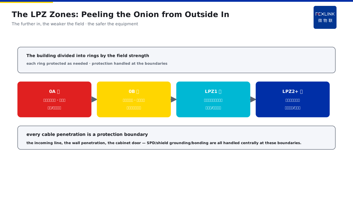
Direct Answer
When reading lightning-protection drawings, LPZ0A and LPZ1 often appear — what exactly do they mean, and why is the building divided this way? The answer: LPZ divides the building into several zones by "the lightning electromagnetic field strength" and "the direct-strike exposure" — zone 0A can suffer a direct strike, zone 0B is protected by air termination but the field is not attenuated, and from zone 1 onward the field is attenuated by shielding and bonding; the zone boundaries are exactly where SPDs, shielding and bonding must be handled centrally.
At a computer room the drawings had LPZ zones, but during construction only one SPD was installed at the main distribution panel; nothing was installed at the network-equipment area (the LPZ1 boundary) and no shielding was done. Once a nearby lightning strike occurred, the induced overvoltage entered the cabinet along the network cable and several boards were damaged. After the SPD stages and shielding were completed per the zone boundaries, the same storms caused no more damage. The key distinction: the zones are not decoration on the drawing but the "map" of the protection measures — each of 0A/0B/1/2 has a different field strength and different protection needs; the zone boundaries (the incoming line, the cabinet entry, the shield penetration) are exactly where SPDs, shielding and bonding must be handled centrally.
Why:
- Why divide into zones: the field strength differs hugely by location, so the density of protection measures should change accordingly;
- What the four zones are: 0A can suffer a direct strike, 0B has air termination but the field is unattenuated, from zone 1 onward attenuated by shielding and bonding;
- What to do at the boundaries: SPD stages, shield grounding and bonding are all concentrated at the boundaries;
- The landing value: by configuring protection per the zones, neither under-protection nor over-spending.
Key insight: "The zones are the 'map' of the protection measures — the building is divided into 0A/0B/1/2 by the field strength, and each zone has different protection needs; the boundaries (the incoming line/cabinet/shield penetration) are exactly where SPDs, shielding and bonding must be handled centrally."
At a factory the LPZ zones on the drawing were treated as decoration and only the main-panel SPD was installed; the boundary at the equipment area was missed. After a nearby strike the control board was damaged, and the investigation found that the induced overvoltage had "slipped in" through the zone boundary. Lesson: a missed boundary protection equals a broken protection chain — once the drawing has zones, the protection must be completed on every boundary.
Overview: run "why divide → what the four zones are → what to do at the boundaries → zones and SPD stages" as one introduction. LPZ (lightning protection zone) is the most basic and practical concept in lightning-protection design: it cuts a building into several rings by "the lightning electromagnetic field strength" and "the direct-strike exposure", each ring with different protection needs, and the protection handled centrally at the boundaries. Understanding the zones means understanding why the SPDs are staged, why the shielding is grounded, and why the bonding is done at the boundaries. The four layers are unfolded below.
A "peel the onion" view of the zones: think of the LPZ as an onion peeled layer by layer from outside in. The outermost 0A is the roof — the lightning strikes directly here and there is no protection at all; 0B is the area under the umbrella of the air-termination rod — the direct strike is blocked but the field is still strong; entering the building is zone 1 — the wall plus the shielding layer weakens the field a notch; then inside the cabinet is zone 2 or 3 — the metal cabinet itself is another shield, and the equipment inside is the safest. Each peeled layer weakens the field a notch and the equipment is safer; and every place where a "layer of onion skin" is penetrated by cables (the incoming line, the wall penetration, the cabinet door) is a boundary where protection must be done. The peel-the-onion view: 0A the roof without protection → 0B air-termination protected but strong field → zone 1 attenuated by the wall shielding → zones 2/3 shielded again by the cabinet; every cable penetration is a protection boundary.
1. Why Divide into Zones: the Field Strength Differs
Step one: in one building, the "lightning environment" differs hugely by location.
The attenuation law of the lightning electromagnetic field:
- The lightning current flowing in the conductor produces an electromagnetic field;
- The field strength attenuates with the distance;
- The shielding layer attenuates further;
- The bonding reduces the potential differences.
Why divide by zone:
- The direct-strike exposure differs (roof vs. interior);
- The field strength differs (outer wall vs. inside the cabinet);
- The protection needs change by zone;
- A one-size-fits-all either under-protects or wastes.
The meaning of the zones:
- Refining "the whole building" into "several zones";
- Each zone protected as needed;
- Clear boundaries and clear duties;
- The drawing is the protection map.
Key insight: "Why divide — the lightning environment differs hugely by location (direct-strike exposure and field strength differ), and the protection needs change by zone; the building is divided into several zones, each protected as needed, avoiding one-size-fits-all under-protection or waste."
2. What the Four Zones Are: 0A/0B/1/2
Step two: one table to understand the four zones.
Zone 0A:
- Can suffer a direct strike;
- No air-termination cover;
- The roof, the open platform, the top of the rod;
- The field not attenuated.
Zone 0B:
- Protected by air termination;
- The direct strike blocked;
- Inside the air-termination range but outside the building;
- The field not attenuated.
Zone LPZ1:
- The first layer after entering the building;
- Attenuated by shielding and bonding;
- The distribution room, the machine-room boundary;
- The field partially attenuated.
Zone LPZ2 and beyond:
- Further attenuated by shielding;
- Inside the cabinet, the equipment layer;
- The field largely attenuated;
- Where the sensitive equipment sits.
Key insight: "The four zones in one sentence — 0A can suffer a direct strike, 0B has air termination but the field is unattenuated, from zone 1 onward attenuated by shielding and bonding, zone 2 even weaker; the further in, the weaker the field, the more sensitive the equipment, the finer the protection."
3. What to Do at the Boundaries: SPD, Shielding, Bonding
Step three: the zone boundaries are the "central processing points" of the protection measures.
The three things at the boundaries:
- SPD stages: an SPD of the corresponding level at each cross-boundary point (relating to KD-0202);
- Shield grounding: the shielding layer grounded at the boundary, cutting the electromagnetic coupling;
- Bonding: the metal pipes/cables entering the building bonded at the boundary.
Why at the boundaries:
- The field strength jumps at the boundary;
- The induced overvoltage enters at the boundary;
- The cable penetration is the weak point;
- The boundary treatment is the most effective.
The typical boundary positions:
- The main incoming line (0B→1);
- The distribution-room entry (1→2);
- The cabinet entry (2→3);
- The shield penetration.
Key insight: "What to do at the boundaries — SPD stages, shield grounding and bonding are all handled centrally at the boundaries; the boundary is where the field jumps and the induced overvoltage enters, so the treatment is the most effective there."
4. From the Zones to the SPD Stages: an SPD at Each Boundary
Step four: the zones directly guide how the SPDs are configured.
The basis of the stages:
- One SPD stage per zone boundary crossed;
- 0B→1: the main incoming line, stage one (T1/T2 by the energy);
- 1→2: the sub-distribution, stage one (T2);
- 2→3: before the equipment, stage one (T2/T3);
- The decoupling distance between the stages must be enough (relating to KD-0202).
Why staged:
- Each stage discharges part of the energy;
- The remaining energy decreases stage by stage;
- The residual voltage on the end equipment is controllable;
- A single stage at the very end is instead dangerous.
The landing points:
- Read the drawing zones first;
- Check the SPD at every boundary;
- Confirm the stage spacing and coordination;
- The end residual voltage within the equipment impulse-withstand voltage.
Key insight: "The zones guide the SPD stages — one SPD stage per boundary crossed (main incoming T1/T2, sub-distribution T2, before the equipment T2/T3); each stage discharges part, and the end residual voltage is controllable; read the zones first and check every boundary."
The on-site practice of finding the boundaries on a drawing: when you get a lightning-protection drawing, do not rush to count the SPDs. Do two things first: one, find the boundaries — trace the 0B/1/2/3 zone lines and see which cables and which equipment cross the boundaries; two, check the boundaries — for every cable position crossing a zone, check whether there is a corresponding SPD, shield grounding and bonding. When the boundaries match, the protection chain is connected; the boundary that is empty is the hidden danger. On site it is common to find that "the drawing zones look nice but the SPD is installed only at the main panel" — the problem lies in not checking boundary by boundary. Reading a drawing, find the boundaries first: trace the zone lines → find the crossing cables → check the SPD/shielding/bonding at every boundary — a matched boundary means a connected protection chain, and an empty boundary is the hidden danger.
5. Product Implementation: Zoned Protection + Online
WeiWuLian products land the zoned protection into verifiable monitoring:
- The FSS Intelligent SPD: staged configuration with visible states;
- SPD monitoring: operations/degradation/leakage records (relating to KD-0161);
- The zoned view: the protection state of every boundary on one screen;
- The data loop: after a strike, verify which stage operated and which stage needs replacement.
The design principle in one sentence: "The zones are the protection map — each of 0A/0B/1/2 differs and the boundaries are handled centrally; the FSS staged configuration + the SPD online monitoring make the protection of every boundary visible."
6. Common Understanding Misjudgments
- "The zones are drawing decoration": wrong. The zones directly guide the SPD/shielding/bonding configuration; a missed boundary is a missed protection.
- "The main-panel SPD alone is enough": wrong. In the end-equipment zone (further in), the field is attenuated but the residual voltage still needs the end SPD.
- "The more shielding the better": overdone. Shield per the zone need; grounding the boundary is more effective than piling materials.
- "The bonding is only at the grounding point": wrong. The cables/metal pipes entering the building are bonded at the boundary, not merely grounded.
- "The more stages the better": wrong. Each stage needs coordination and decoupling distance; adding stages blindly introduces new problems.
Scope and Limitations
This article explains the basic LPZ concepts (the meaning of 0A/0B/1/2, the boundary handling, the relation to the SPD stages), applicable to reading lightning-protection drawings and getting started with protection configuration. The specific zone details, shielding and bonding practices follow GB 50057-2010 and IEC 62305-1; this article explains only the concepts and the logic. All cases are anonymized (a computer room/a factory) and do not refer to any specific customer.