 FEXLINK Research Institute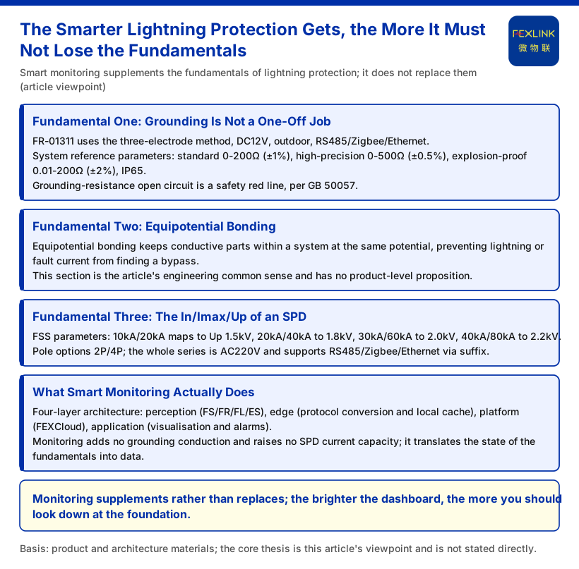
In recent years lightning-protection systems have grown "smarter": field devices report their status, gateways push data outward, and platforms draw trends and raise alarms. That makes one inference feel natural — if everything can be watched online, can the "old engineering" items such as grounding, equipotential bonding and SPD parameters be left to the smart system to catch? This article argues against exactly that inference. Read it as opinion and verify per project.
First, Separate Opinion from Fact
The error an opinion article is most prone to is letting its own assertions blend into product facts. This is not formalism; it lets readers tell at a glance what can be quoted as-is and what they must judge for themselves. Three fundamentals come first, then where smart monitoring fills in.
Fundamental One: Grounding Is Not a One-Off Job
Grounding is often treated as concealed work that "needs no attention once installed", yet it is the foundation of a lightning-protection system. Among the FR grounding resistance monitors listed in the knowledge base, the FR-01311 uses three-electrode measurement, is powered at DC12V and installed outdoors, and supports RS485/Zigbee/Ethernet communication; its model rule separates the measurement principle into the loop method (code 2) and the three-point method (code 3). The same section also gives system-level reference parameters: standard monitoring unit 0–200 Ω (±1%), high-precision type 0–500 Ω (±0.5%), explosion-proof type 0.01–200 Ω (Ex d IIB T4/T6 Gb, ±2%), protection rating IP65, operating temperature -20–70 °C, an intelligent gateway able to mount ≥128 points (cascadable), data cache ≥15 days, and DC9–36V wide-voltage input.
More worth remembering than the numbers is their priority. The knowledge base lists "abnormal open circuit of grounding resistance" as the red line — a guard rule that cannot be bypassed and whose threshold no one may raise, on the basis of standard GB 50057. That means grounding status in the system is not an ordinary measuring point but a floor. However smart the equipment is, it cannot "calculate" an already-open grounding grid back into service — monitoring can only tell you it has failed; it cannot conduct on its behalf. This point is the starting point of every judgement that follows.
Fundamental Two: Equipotential Bonding
Equipotential bonding is as much a fundamental as grounding. In engineering practice, equipotential bonding keeps conductive parts within a system at the same potential, preventing a lightning strike or fault current from seeking a bypass path through a potential difference; together with grounding it forms the channel that "conducts energy safely away".
It is written out separately because smart technology most easily creates an illusion: if grounding resistance on screen looks normal, the whole discharge path is assumed fine. Yet the "invisible" stage of potential bonding is exactly the part monitoring finds hardest to cover, and the part that must least be forgotten. This is opinion, not a product conclusion; the specific method must still be determined by site survey and applicable standards.
Fundamental Three: The In/Imax/Up of an SPD Cannot Be Bypassed by "Smart"
If grounding is the channel, an SPD is a gate on that channel, and the gate's selection is decided by a few basic parameters. The FSS intelligent surge protective device in the knowledge base gives explicit In/Imax and Up combinations: 10 kA/20 kA maps to Up 1.5 kV, 20 kA/40 kA to 1.8 kV, 30 kA/60 kA to 2.0 kV, and 40 kA/80 kA to 2.2 kV; pole configurations are 2P/4P, the whole series is powered at AC220V, and RS485/Zigbee/Ethernet communication can be chosen by suffix.
Laying out these parameters is meant to mark a boundary: smart monitoring can tell you an SPD's status and lifetime trend, but it will not change the device's own current-carrying capacity or voltage protection level. In/Imax decides how large a surge it can withstand, and Up decides how low it clamps the residual voltage — both are essentially fixed at the moment of selection. Monitoring data is "after-the-fact status", not a "substitute for parameters". Choosing casually just because monitoring was installed hands the fundamentals over to a dashboard.
What Smart Monitoring Actually Does: Supplement, Not Substitute
Where, then, is the value of smart technology? The knowledge base defines the monitoring system as a four-layer architecture of perception, edge, platform and application layers: the perception layer is made up of FS/FR/FL/ES series monitoring modules, smart electricity meters and sensors; the edge layer handles protocol conversion, edge computing and local caching; the platform layer is FEXCloud; and the application layer delivers Web/App visualisation, alarm management and analytical reports. Along this chain, the monitoring elements of the FS surge protective device monitor span remote signalling, air-switch status, grounding status, lightning-strike count, leakage current, temperature, voltage and lifetime estimation, with leakage current 50.0–1200.0 μA (±10 μA), voltage 0–400.0 V (±0.1 V), temperature -20–100 °C (±1 °C), lightning-strike count 0–9999 (minimum trigger 0.1 kA) and lifetime estimation 0–100%; the ESM intelligent lightning-protection monitoring terminal adds humidity and other elements on that basis. Data is sent up through the FG lightning-protection intelligent gateway (protocol-conversion type; downlink RS485/Zigbee, uplink Ethernet, DC12V; models FG-0221-ER/EZ), with protocols arranged per the matrix: device downlink includes Modbus RTU (RS485), Zigbee (Modbus) and LoRa; device uplink includes Modbus TCP/MQTT (Ethernet, 4G); and IEC 61850 is optional at gateway level.
These capabilities solve a "can we see it" problem: conditions once found only by inspection are now observed continuously, and lightning events once hard to trace have a countable record. But note what they do not solve — not one ohm of grounding conduction is added, nor one level of SPD current-carrying capacity raised. Monitoring "translates" the state of the fundamentals into data; it does not "upgrade" the fundamentals themselves into software.
What This Article Does Not Claim
Stating the boundaries clearly matters more than filling out conclusions. This article does not claim the following:
First, it does not claim that smart technology is without value. On the contrary, it turns grounding and SPD status from spot checks into continuously visible state, which is exactly the supplementary value this article acknowledges.
Third, it does not claim any parameter, certification or effect beyond those cited. The models, ranges and In/Imax/Up values in the text are limited to those explicitly listed in the knowledge base, and no unlisted model, unspecified parameter range or protection effect is inferred from them.
Fourth, it involves no specific project's grounding effect, SPD protection effect or promise of immunity to lightning, and no figures such as platform usage rates or operational statistics.
In other words, this article addresses the "relationship between primary and secondary concerns at the methodological level". It is not an endorsement of any engineering protection capability, nor a basis for procurement or acceptance. An implementation scheme must still be verified item by item against the site boundary and applicable standards.
Conclusion
Making a lightning-protection system smart is worth doing; but what it changes is how we obtain status, not the basic physics of lightning protection. Grounding must genuinely conduct, equipotential bonding must genuinely hold, and an SPD's In/Imax and Up must genuinely be chosen correctly — these fundamentals decide whether the system can withstand a strike when it comes; smart monitoring decides whether we can find out sooner that it could not. Put the two in the right relationship: monitoring supplements, it does not replace; the brighter the dashboard, the more important it is to look at the foundation.