 FEXLINK Research Institute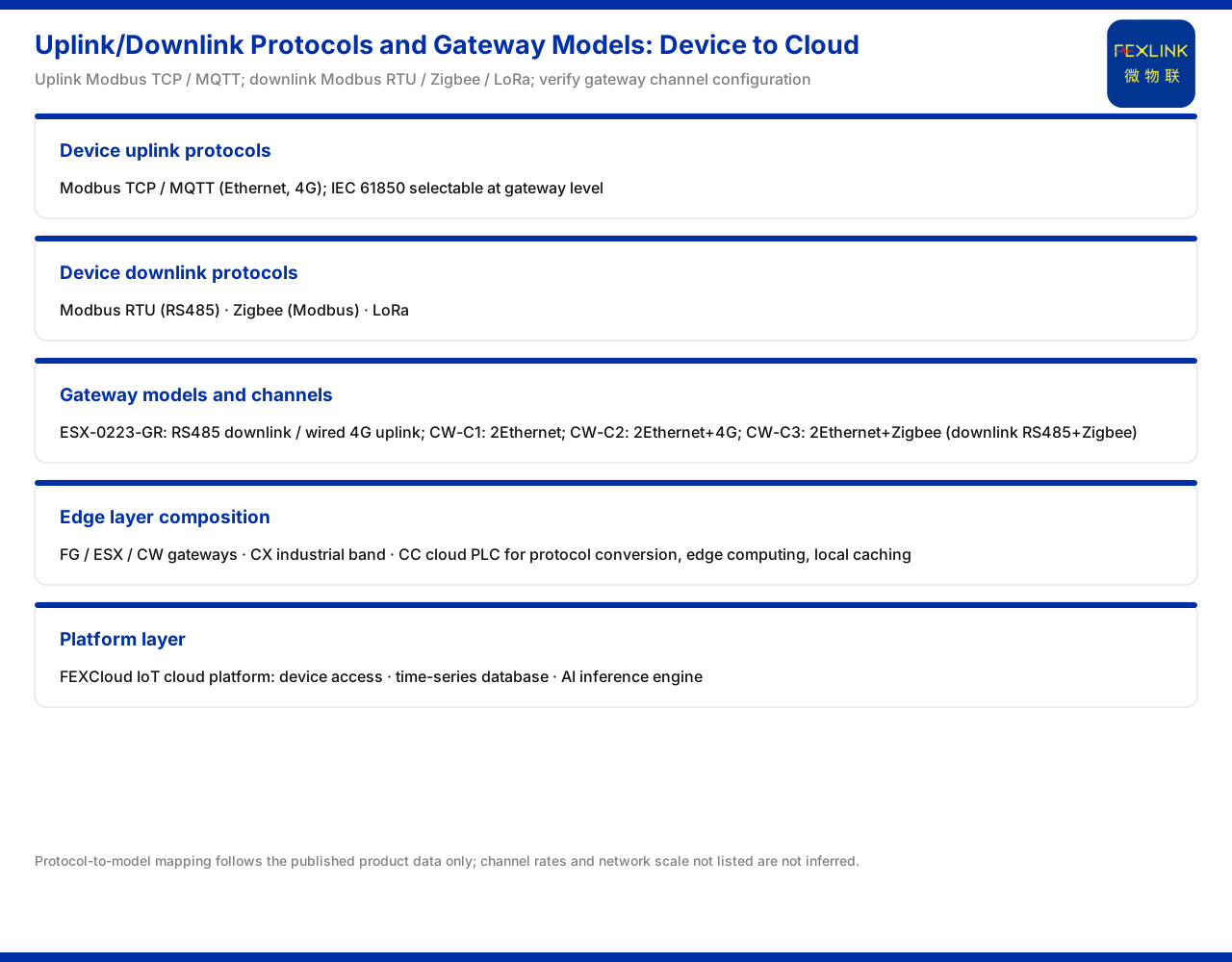
Direct answer
In a monitoring system, data travelling from the field to the platform does not follow one direction but two: downlink to the device and uplink to the platform. Understanding the communication capability of a scheme is not about memorising protocol names but about distinguishing which channel runs in which direction and which device carries it. Based on the wording listed in the product documentation, this article explains the device uplink and downlink protocol matrix, the channel configuration of typical gateway models, and the placement of protocol conversion and data aggregation under the four-layer architecture; it infers no networking detail of any specific project.
1. Uplink and downlink: two channels in different directions
The communication protocol matrix in the product documentation divides protocols into two groups, device uplink and device downlink. Uplink means data passing from the field side to the platform side, and downlink means control or collection commands passing from the gateway or platform side to the device. The protocol sets of the two directions are not the same, and this is what networking design must distinguish first.
Once the directions are clear, many questions have answers: during selection one looks at which protocols in which direction a device supports, and during design one looks at whether the two directions can interconnect at the same gateway. If the uplink and downlink protocols do not match, the link breaks in the middle. The product documentation gives the matrix classification, and this article does not expand the implementation details or conversion rules of each protocol.
2. Device uplink protocols
The product documentation states that the device uplink protocols are Modbus TCP and MQTT, which can run over Ethernet and 4G and form two parallel choices for a gateway to connect upward to the platform; at the gateway level, IEC 61850 is also optional. In other words, the uplink backbone is two protocols plus two bearer types, with one additional option facing a particular domain.
The two parallel choices correspond to different networking preferences: one leans toward the generality of industrial sites, and the other toward message-based platform connection. The bearers being Ethernet or 4G show that the uplink can run over wire or wirelessly. The gateway-level optional IEC 61850 then extends the choice to particular scenarios such as substations. The product documentation lists only the protocol names and the optional level, and this article does not infer the applicable conditions or performance differences of each protocol.
3. Device downlink protocols
The product documentation states that the device downlink protocols are Modbus RTU (RS485), Zigbee (Modbus), and LoRa. The three protocols correspond to three connection modes on the field side: wired serial, short-range wireless self-organising network, and long-range wireless.
The diversity of the downlink comes from differences among field devices. RS485 suits fixed wiring and short-distance multi-device connections; Zigbee suits dense points; and LoRa suits situations where points are scattered and distances are long. A gateway must be able to accommodate several downlink modes in order to bring devices with different interfaces into one network. Viewing the downlink protocols together with capabilities such as the temperature monitoring above explains why wireless temperature data can enter the same protocol system through LoRa. The product documentation gives the protocol list, and this article does not infer the rate or networking scale of each protocol.
4. Gateway models and channel configuration
The product documentation states that the intelligent edge-computing gateway (ESX-0223-GR) communicates downward over RS485 and upward over wired 4G, with an access capability of 30 devices and 2000 data points. This gives one typical configuration of wired downlink and wireless uplink.
The industrial gateway (CW series) offers a more finely divided choice. The product documentation states that the industrial gateway (CW-C1) has two Ethernet ports; the industrial gateway (CW-C2) has two Ethernet ports plus 4G; and the industrial gateway (CW-C3) has two Ethernet ports plus Zigbee. Correspondingly, CW-C1 uplinks over Ethernet, CW-C2 uplinks over Ethernet plus 4G, and CW-C3 uplinks over Ethernet with a downlink of RS485 plus Zigbee. The differences among the three models precisely reflect the combination of uplink bearer and downlink mode. The product documentation gives the channel-configuration wording, and this article does not infer the project types each model suits.
5. The edge layer: protocol conversion and local caching
The product documentation states that the edge layer of the general four-layer monitoring-system architecture is carried by the FG, ESX, and CW gateways, the CX industrial wearable, and the CC cloud PLC, which handle protocol conversion, edge computing, and local caching. The duty of the edge layer is to translate the diverse field data into a unified form that can be sent upward.
Protocol conversion corresponds to the interconnection of uplink and downlink; edge computing corresponds to completing preliminary processing before data goes upward; and local caching corresponds to temporarily storing data when the network is interrupted and retransmitting after recovery. These three capabilities explain why the edge layer cannot be omitted: without it, field protocols cannot converge into the platform, and data cannot be preserved when the link fluctuates. The product documentation gives the edge-layer devices and duties, and this article does not expand the computing power and cache capacity of each device.
6. The platform layer: FEXCloud
The product documentation states that the platform layer is the FEXCloud IoT cloud platform, which handles three classes of function: device access, time-series database, and AI inference engine. The platform layer is where data is finally collected and intelligently processed.
Device access corresponds to being connectable; the time-series database corresponds to being storable and quickly queryable; and the AI inference engine corresponds to being computable. The three echo the uplink protocols above: data enters the platform through the uplink channel, first completes device access, then is written into the time-series database, and is subsequently called by the inference engine. Viewing the platform layer separately from the edge layer makes clear the division of the edge handling aggregation and the platform handling intelligence. The product documentation gives the platform function composition, and this article does not infer its deployment form or capacity indicators.
7. Channel placement under the four-layer architecture
Bringing the four-layer architecture together: the perception layer is the various monitoring modules, smart meters, and sensors; the edge layer is the gateways, the industrial wearable, and the cloud PLC; the platform layer is FEXCloud; and the application layer is the visualisation and alarms facing users.
The protocol channels run precisely through these layers. The downlink protocols connect the devices of the perception layer into the edge layer, the uplink protocols send the edge-layer data into the platform layer, and the platform layer then outputs results to the application layer. Understanding this vertical path makes clear why selection must check both the downlink protocols a device supports and the uplink protocols a gateway supports. The product documentation gives the duties of the four layers, and this article draws no inference about the networking scheme of a specific project.
Scope and limitations
First, this article restates only the wording listed in the product documentation, and its factual boundary is limited to: the device uplink protocols Modbus TCP and MQTT (Ethernet, 4G), with gateway-level optional IEC 61850; the device downlink protocols Modbus RTU (RS485), Zigbee (Modbus), and LoRa; the intelligent edge-computing gateway (ESX-0223-GR) with downward RS485 and upward wired 4G, accessing 30 devices and 2000 data points; the industrial gateway (CW-C1) with two Ethernet ports, the industrial gateway (CW-C2) with two Ethernet ports plus 4G, and the industrial gateway (CW-C3) with two Ethernet ports plus Zigbee, whose uplinks are respectively Ethernet, Ethernet plus 4G, and Ethernet (with a downlink of RS485 plus Zigbee); the edge layer of the four-layer architecture carried by the FG, ESX, and CW gateways, the CX industrial wearable, and the CC cloud PLC handling protocol conversion, edge computing, and local caching; and the platform layer FEXCloud handling device access, time-series database, and AI inference engine.
Second, this article does not infer the rate, concurrency, or security mechanism of each protocol, nor the networking structure or link performance of any specific project.
Third, the protocol matrix, channel configuration, and four-layer architecture are product-documentation wording, and field networking and device counts belong to engineering-design judgement.
Fourth, specific selection and configuration should follow the latest product documentation, the relevant standards, and the project scheme.