 FEXLINK Research Institute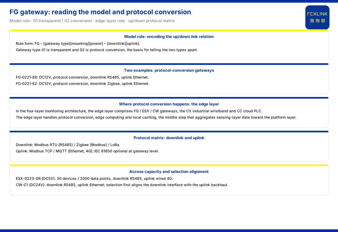
Direct answer
For a piece of field data to enter the platform, two things must be settled first: by what protocol it travels upward, and what the gateway converts the downstream device protocol into. The approach given by the product knowledge base is to write the answer into the model number: the model rule of the FG lightning-protection smart gateway encodes, segment by segment, the gateway type, the mounting method, the power supply, the downlink and the uplink, so that reading the model reveals its uplink/downlink combination. The gateway type falls into two classes, transparent transmission and protocol conversion, and protocol conversion takes place at the edge layer of the general monitoring-system architecture, carried by devices such as the lightning-protection smart gateway and the intelligent edge-computing gateway. Devices commonly use Modbus RTU, Zigbee and LoRa on the downlink, and Modbus TCP or MQTT on the uplink over Ethernet or 4G, with IEC 61850 optional at the gateway level. This article explains how to read the model, where the protocol is converted, and the uplink/downlink relationship to align during selection, and it marks the boundary of the material.
1. Model rule: encoding the uplink/downlink relationship
The product knowledge base records that the model rule of the FG lightning-protection smart gateway is "FG – gateway type, mounting method, power supply – downlink, uplink". That is, the first half of the model describes the device itself and the second half describes how it connects to the two sides above and below.
The advantage of this writing is readability. During procurement and wiring one need not first open the manual, because the model already distinguishes what the downlink side connects to and what the uplink side uses. For system integration, this layer of information saves one confirmation. In the model rule the gateway type takes only two values, 01 and 02, corresponding respectively to transparent transmission and protocol conversion, which is the starting point for understanding the division between the two gateway classes.
2. Transparent transmission and protocol conversion: two gateway types
Gateway type 01 is transparent transmission and 02 is protocol conversion. Transparent transmission means the data passes through the gateway in its original form and the gateway does not change its protocol form; protocol conversion means the gateway performs one protocol translation between the downlink and the uplink.
The two classes face different scenarios. When the field device and the platform use the same protocol, transparent transmission suffices; when the field device uses a downlink such as RS485 or Zigbee while the platform side needs another protocol over Ethernet, protocol conversion is needed to bridge them. The product knowledge base places the two together in the model rule, showing that the first step of selection is not to look at the number of interfaces but to determine whether conversion is needed at all.
3. Comparison of two specific models
The model table of the product knowledge base gives two examples that confirm the reading above. The FG lightning-protection smart gateway (FG-0221-ER) is powered at DC12V, has a data-transmission mode of protocol conversion, with RS485 downlink and Ethernet uplink. The FG lightning-protection smart gateway (FG-0221-EZ) is likewise DC12V and protocol conversion, the difference being a Zigbee downlink with Ethernet still on the uplink.
Set side by side, the difference is concentrated in the "downlink" segment: ER corresponds to RS485 and EZ to Zigbee. Both use Ethernet on the uplink, showing that they are consistent on the platform side and differ only in what is connected on the line side. This is exactly the value of the model encoding: under the same power supply and the same gateway type, changing one field corresponds to another fieldbus.
4. Protocol conversion happens at the edge layer
Protocol conversion is not a matter for the platform side but a responsibility of the edge layer. The product knowledge base divides the general monitoring-system architecture into perception layer, edge layer, platform layer and application layer, where the edge layer is made up of the lightning-protection smart gateway, the intelligent edge-computing gateway, the industrial wearable and the cloud PLC, with the duties of protocol conversion, edge computing and local caching.
Keeping this layer's responsibility clear prevents looking in the wrong direction during troubleshooting. If the downlink protocol will not connect, the problem is between the edge layer and the perception layer; if the uplink protocol will not connect, the problem is between the edge layer and the platform layer. Since protocol conversion is completed at the edge layer, the gateway is the hub of this segment. The product knowledge base also shows that protocol conversion is one of the three duties of the edge layer, alongside edge computing and local caching.
5. Communication protocol matrix and common suffixes
The specific protocol names are given by the communication protocol matrix of the product knowledge base. Device downlink protocols include Modbus RTU (RS485), Zigbee (Modbus) and LoRa; device uplink protocols include Modbus TCP and MQTT (over Ethernet or 4G), with IEC 61850 optional at the gateway level.
The common suffixes are a shorter way of marking within the model. The product knowledge base records: -R is RS485 (Modbus), -E is Ethernet (MQTT) and -Z is Zigbee (Modbus), with some products offering 4G (MQTT) as an option. This shows that MQTT is not something outside the physical link but is carried over an uplink such as Ethernet or 4G. Reading the suffixes against the protocol matrix, the model fields and the protocol names line up one to one.
6. Access capability of the edge-computing gateway
Beyond protocol conversion, the edge layer also has devices that carry edge computing. The model table of the product knowledge base records that the ESX intelligent edge-computing gateway (ESX-0223-GR) is powered at DC5V, with an access capability of 30 devices and 2000 data points, RS485 downward and wired 4G upward; the CW industrial gateway (CW-C1) is powered at DC24V, with RS485 downward and Ethernet upward.
These parameters show that the edge-computing gateway and the lightning-protection smart gateway sit at similar positions on the link but with different emphases: the former stresses access scale and local processing, the latter stresses protocol conversion in a protection scenario. During selection one first checks whether the device count and data points are sufficient, then aligns the power supply and the uplink/downlink modes.
7. Align uplink and downlink before selection
Taken together, selection can proceed in one order: first determine the protocol of the field devices, then see what protocol the platform side needs, and on that basis decide between transparent transmission and protocol conversion; next check whether the power supply and mounting method match the field conditions; and finally confirm whether the rated access capability covers the field device count and data points.
The basis for this order comes from the model rule itself: it writes the gateway type, power supply, downlink and uplink into the number, showing that these are exactly the items that must be determined first during selection. The product knowledge base gives no single answer corresponding to specific field conditions, so this article explains only the alignment relationship and does not decide for the reader which model a given site should choose.
Scope and limitations
First, this article only restates the content listed in the product knowledge base; the factual boundary is limited to the model rule and model table of the FG lightning-protection smart gateway, the general four-layer monitoring-system architecture, the communication protocol matrix, the common suffixes, and the model-table records of the ESX intelligent edge-computing gateway and the CW industrial gateway.
Second, in the model rule of the FG lightning-protection smart gateway, gateway type 01 as transparent transmission and 02 as protocol conversion, and the power supply, protocol-conversion mode, downlink and uplink of FG-0221-ER and FG-0221-EZ, are quoted as recorded in the product knowledge base; this article does not infer unlisted model combinations.
Third, that the edge layer is made up of the lightning-protection smart gateway, the intelligent edge-computing gateway, the industrial wearable and the cloud PLC, with the duties of protocol conversion, edge computing and local caching, is quoted as recorded in the product knowledge base.
Fourth, the downlink Modbus RTU (RS485), Zigbee (Modbus) and LoRa and the uplink Modbus TCP, MQTT (Ethernet, 4G) and IEC 61850 (gateway level, optional) of the communication protocol matrix, together with the common suffixes -R, -E and -Z and the optional 4G (MQTT) of some products, are quoted as recorded in the product knowledge base.
Fifth, the 30 devices and 2000 data points of the ESX intelligent edge-computing gateway and the power supply and uplink/downlink of the CW industrial gateway are quoted as recorded in the product knowledge base; this article does not infer other access scales or field performance.
Sixth, this article explains only how to read the model, where protocol conversion takes place and the alignment relationship for selection; it provides no specific engineering networking, address planning or setting scheme.