 FEXLINK Research Institute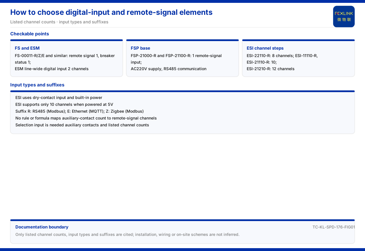
Direct Answer
On how to select switching-value and remote-signal elements, the answer in the product documentation falls into two parts: the channel counts actually provided by each product, and whether the documentation gives a rule for choosing the channel count by the number of auxiliary contacts. On channel counts, the model table of the FS surge protective device monitor (FS-00011-R/Z/E, FS-03211-R/Z/E, FS-33211-R/Z/E) lists remote signal and breaker status separately, both at 1; the switching value of the ESM intelligent lightning-protection monitoring terminal is 2 channels across the whole series; the remote-signal input of the FSP SPD lightning-protection base (FSP-21000-R) and (FSP-21100-R) is 1 channel, with AC220V supply and RS485 communication; the ESI digital-input status monitor (ESI-22110-R) has 8 channels, the ESI digital-input status monitor (ESI-11110-R/21110-R) has 10 channels, and the ESI digital-input status monitor (ESI-21210-R) has 12 channels. On rules, the documentation lists only these channel counts and gives no decision rule or formula for choosing the remote-signal channel count by the number of auxiliary contacts.
This article explains the listed channel counts, communication suffixes, and input methods of the remote-signal and switching-value elements and marks out what the documentation does not expand.
1. Remote Signal and Breaker Status of the FS
The documentation lists a switching-value position in the model rule of the FS surge protective device monitor and lists remote signal and breaker status as two separate items in the model table. For the FS models above, remote signal is 1 and breaker status is 1.
Splitting remote signal and breaker status into two items shows that they acquire two different state quantities: remote signal reflects the state signal of an auxiliary contact, and breaker status reflects the circuit-breaker position. Placed side by side, they make the state information of an FS model more complete. The FS model lists the switching value as one position segment, and the model table expands that segment into remote signal and breaker status. The correspondence between the segment and its expanded items is the relation to clarify first when reading the state configuration of an FS model.
2. Switching Value of the ESM
The documentation lists a switching-value column in the model table of the ESM intelligent lightning-protection monitoring terminal, and the whole series (ESM-21001-R to ESM-21312) has 2 switching-value channels. Compared with the 1 remote-signal channel of the FS, the ESM provides more channels for switching values.
The channel difference corresponds to different access needs. The more switching-value channels, the more state signals can be connected at once. During selection, take the number of auxiliary contacts to be connected as the input and compare it against the model's channel count. The ESM switching value is uniformly 2 channels across the series, unlike the FS stepping by model. A uniform channel count means selection need not compare switching-value differences inside the ESM but only confirm other elements; a stepped channel count requires fixing the count before locating the model.
3. Remote-Signal Input of the FSP Base
The documentation lists the remote-signal input of the FSP SPD lightning-protection base (FSP-21000-R) and (FSP-21100-R) as 1 channel, with AC220V supply and RS485 communication. The base form differs from the monitoring module, and its remote signal reflects the state of the SPD itself.
Although both belong to SPD-related products, the 1 remote-signal channel of the FS and the 1 remote-signal input of the FSP are numerically the same but differ in product form and purpose. Selection should decide between module and base according to the existing SPD structure on site. The base form means the FSP usually works with an existing SPD, and its remote-signal input serves monitoring of the SPD state. Choosing a base or a module depends on the existing structure and the type of state quantity to be acquired.
4. Channel Steps of the ESI
The documentation distinguishes models of the ESI digital-input status monitor by switching-value channel count: the ESI digital-input status monitor (ESI-22110-R) has 8 channels, the ESI digital-input status monitor (ESI-11110-R/21110-R) has 10 channels, and the ESI digital-input status monitor (ESI-21210-R) has 12 channels. Unlike the single-digit channel counts of the FS and ESM, the ESI faces centralized monitoring of more state quantities.
The multiple channel steps let the ESI cover access needs from small to fairly large scale. Placing 8, 10, and 12 channels side by side shows a clear gradient in channel count for state monitoring. The small gap among the three steps indicates that the ESI faces medium-scale centralized access of state quantities rather than very large scale. Comparing this gradient with the single-digit channel counts of the FS and ESM helps judge the access-scale range of different products.
5. Input Method and Supply Constraint
The documentation lists the input method of the ESI as dry-contact input with built-in power, and notes that at 5V supply it can only serve 10 input channels. This constraint shows that the channel count depends not only on the model but also on the supply condition.
Dry-contact input means a passive contact signal is connected, which has direct meaning for field wiring. Reading the input method together with the supply constraint avoids exceeding the actually available channel count during selection.
6. Selection of the Communication Suffix
The general suffix rule in the documentation is that R corresponds to RS485 (Modbus), E to Ethernet (MQTT), and Z to Zigbee (Modbus). The communication method of switching-value and remote-signal modules is chosen by suffix, so the same function can have different uplink interfaces.
The suffix separates function from communication: first determine how many remote-signal or switching-value channels are needed, then choose the suffix according to field network conditions. A model obtained this way satisfies both the channel-count and communication requirements. Suffix and channel count belong to two dimensions: the channel count determines how many state quantities can be connected, and the suffix determines how these state quantities go upward. Confirming the two dimensions separately avoids one being sacrificed for the other.
7. From Channel Count to Selection Order
Combining the product entries yields a reading supported by the documentation: first confirm the type of state quantity to be connected — remote signal and breaker status are different signals and should be matched separately; then confirm the quantity — the FS and FSP are single-digit, the ESM is 2 channels, and the ESI is 8, 10, and 12 channels; finally confirm the input method and supply condition — the ESI uses dry-contact input and built-in power, and at 5V supply it can only serve 10 input channels. The communication suffix is chosen after the function is fixed.
This order checks the type, quantity, and electrical condition of the state quantities separately. The documentation guarantees only that the listed channel counts of each model are retrievable; it does not guarantee a formula that derives the channel count directly from the number of auxiliary contacts. A selection conclusion should therefore return to the model entry itself.
8. The Documentation Boundary
The documentation lists only the 1 remote-signal input of the FSP, the 2 switching-value channels of the ESM, and the 8, 10, and 12 switching-value channels of the ESI, and gives no decision rule or formula for choosing the remote-signal channel count by the number of auxiliary contacts. This article therefore provides no formula relating contact count to channel count.
Actual selection should take the number of auxiliary contacts to be connected on site and the listed channel counts of each model as inputs and supplement the judgment outside the documentation. This article's boundary stops at the listed channel counts, input methods, and suffixes.
Scope and Limitations
First, this article restates only what the product documentation lists. The remote signal and breaker status of the FS, the switching value of the ESM, the remote-signal input of the FSP, the channel counts and input method of the ESI, and the general suffix are cited as written.
Second, this article does not infer the installation method, wiring details, or protection rating of each product, and does not derive an on-site configuration from channel counts.
Third, this article gives no rule or formula for choosing the remote-signal channel count by the number of auxiliary contacts, because that decision basis is outside the factual boundary of the product documentation.
Fourth, the mapping of the general suffix is cited as listed; this article does not extend to other communication forms beyond the suffix.