 FEXLINK Research Institute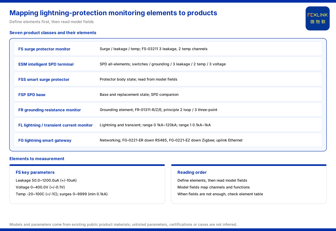
Direct answer
Mapping lightning-protection monitoring elements to specific products depends not on memorizing model numbers but on reading the model rules and element tables. The product-line overview of the product knowledge base lists intelligent lightning protection as seven categories: the FS surge protective device monitor, the ESM intelligent lightning-protection monitoring terminal (SPD monitor), the intelligent surge protective device, the SPD lightning-protection base, the FR grounding resistance monitor, the FL lightning current/transient current monitor, and the FG lightning-protection smart gateway. Each category corresponds to a group of monitoring elements and can be traced back through its model fields or element table. For example, the model rule of the FS surge protective device monitor (FS-03211) writes voltage channels, leakage-current channels, temperature channels, digital inputs, and grounding/lightning as fields, with 3 leakage-current channels and 2 temperature channels; the model rule of the FR grounding resistance monitor (FR-01311-R/Z/E) encodes signal acquisition, detection principle, mounting, and supply, where detection principle 2 is the loop method and 3 is the three-point method; and the FL lightning current/transient current monitor splits its detection range into two ranges, 1 kA to 120 kA and 0.1 kA to 1 kA. In short, element mapping is a comparison process of "define the element first, then read the fields."
1. First, distinguish what each of the seven categories manages
The first step in mapping is knowing which products are available. The product-line overview lists intelligent lightning protection as seven categories spanning monitoring, protection, grounding, and gateways: the FS surge protective device monitor, the ESM intelligent lightning-protection monitoring terminal, the intelligent surge protective device, the SPD lightning-protection base, the FR grounding resistance monitor, the FL lightning current/transient current monitor, and the FG lightning-protection smart gateway. This classification itself gives a coarse correspondence between elements and products: to monitor the state of a surge protective device, look at the FS and ESM families; to monitor grounding resistance, look at FR; to monitor lightning and transient current, look at FL; to aggregate data for the uplink, look at FG. Only after this layer of correspondence is established do model fields have somewhere to land.
2. FS: monitoring elements written into the model fields
The model rule of the FS surge protective device monitor is itself a mapping table. The product knowledge base records that its model is built from five segments—voltage channels, leakage-current channels, temperature channels, digital inputs, and grounding/lightning—plus a communication segment; taking FS-03211 as an example, it provides 3 leakage-current channels and 2 temperature channels. This means that when the monitoring element is "leakage current and temperature of several circuits in one distribution section," the channel counts can be checked directly against the fields rather than hunted for in a datasheet. Beyond channel counts, the product knowledge base gives the FS key parameters: leakage current 50.0 to 1200.0 μA (±10 μA), voltage 0 to 400.0 V (±0.1 V), temperature -20 to 100 °C (±1 °C), and lightning count 0 to 9999 strokes (minimum trigger 0.1 kA). The parameter ranges decide whether the product can cover the field magnitude, and they are the second filter in the mapping.
3. ESM: a terminal for full-element SPD monitoring
If the monitoring elements go beyond leakage current and temperature and require coverage of several SPD states, the ESM intelligent lightning-protection monitoring terminal (SPD monitor, full-element) should be considered. The product knowledge base records that its model rule is built from five segments—supply, display, phase count, current parameters, and version—plus a communication segment, and that its element table covers digital inputs, grounding state, lightning count, leakage current (1 or 3 channels), temperature (1 or 2 channels), and voltage (1 or 3 channels). Compared with FS, the ESM has a wider element surface, and the "full-element" positioning is exactly what these options express. When mapping elements, the items a site must monitor should be checked one by one against this element table to see which fall inside the options; items inside the table can be matched, and items not listed should not be filled in on one's own.
4. FR: measurement principle and installation conditions encoded
Mapping the grounding-resistance monitoring element lands on the FR grounding resistance monitor. The product knowledge base records that its model rule is built from four segments—signal acquisition, detection principle, mounting, and supply—plus a communication segment, where detection principle 2 is the loop method and 3 is the three-point method. This shows that grounding monitoring does not have only one measurement method, and that selection must align the measurement principle available on site with the model fields. The product knowledge base also records that the FR grounding resistance monitor (FR-01311-R/Z/E) is a DC12V outdoor unit using the three-electrode method, with communication selectable among RS485, Zigbee, or Ethernet. Because mounting and supply are written into the model, mapping must also verify that the site has the corresponding installation and supply conditions.
5. FL: distinguishing lightning current from transient current by detection range
Monitoring of lightning and transient current relies on the FL lightning current/transient current monitor. The product knowledge base records that its detection range has two settings: one is 1 kA to 120 kA and the other is 0.1 kA to 1 kA; function options include peak, peak plus energy, waveform, and waveform plus energy. When mapping, first judge whether the target belongs to the lightning-current magnitude or to the smaller transient-current magnitude, choose the corresponding range, and then choose the function option as needed. This category is mapped not by channel count but by magnitude and function combination; once magnitude and function are aligned, the mapping is complete.
6. FG: does not acquire elements, only sends data upward
One of the seven categories does not acquire monitoring elements directly but handles aggregation. The product knowledge base records that the FG lightning-protection smart gateway (FG-0221-ER) is built from three segments—gateway type, mounting, and supply—plus a downlink segment and an uplink segment; FG-0221-ER uses RS485 downlink and Ethernet uplink, and FG-0221-EZ uses Zigbee downlink and Ethernet uplink. In element mapping, this category does not take part in deciding "what to acquire" but in deciding "how to send what has been acquired": the downlink used by the front-end monitoring devices determines which gateway model is chosen. Only when the gateway is put back into the whole picture does the mapping close into a workable link.
7. Reducing the element mapping into an ordered sequence
Taken together, the mapping from lightning-protection monitoring elements to products can be reduced to an ordered sequence. Step one, list the elements to be monitored: surge protective device state, grounding resistance, lightning and transient current, or merely aggregation and uplink. Step two, make a coarse correspondence across the seven categories and determine the candidate product families. Step three, read the model rule or element table of the candidates and land each element on a field, such as the voltage/leakage/temperature/digital and grounding/lightning fields of FS or the digital/grounding/leakage/temperature/voltage fields of ESM. Step four, filter by key parameters such as the FS leakage, voltage, temperature, and lightning-count ranges, or the FL detection-range setting. Step five, verify installation and supply conditions such as the FR mounting and supply fields. Step six, choose the gateway downlink and uplink to connect the link. Following this sequence answers "which product category, which field group, and which parameter range the element corresponds to."
Scope and limitations
First, this article restates only what the product knowledge base lists, and the factual boundary is limited to the product-line overview, the model rules and element tables of the products, key parameters and detection ranges, and the gateway downlink and uplink; it introduces no unlisted parameter, certification, or case.
Second, the seven-category composition of the product line, the FS model rule and the 3 leakage-current and 2 temperature channels of FS-03211, and the FS key parameters are cited as the product knowledge base lists them.
Third, the ESM model rule and element coverage, the FR model rule and detection-principle codes, the supply, mounting, measurement principle, and communication of the FR grounding resistance monitor (FR-01311-R/Z/E), the FL detection ranges and function options, and the FG model rule and the downlink/uplink of FG-0221-ER and FG-0221-EZ are cited as the product knowledge base lists them.
Fourth, the models in the text are those already recorded in the materials and are used to explain how to read the model rules; this article does not infer the specifications of unlisted models from them, nor does it infer performance or effects.
Fifth, the product knowledge base gives no conversion between monitoring elements and configured quantities; this article records that boundary and does not infer an unlisted selection formula or point count from it.
Sixth, this article explains only how to read the mapping from elements to products and provides no specific engineering selection or configuration calculation; related conclusions must be confirmed against site conditions and the project scheme, and the latest product materials and project scheme always prevail.