 FEXLINK Research Institute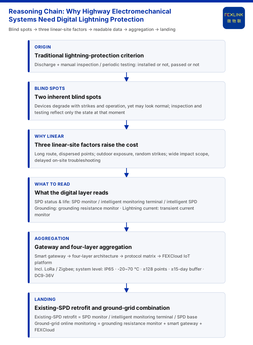
Why Do Highway Electromechanical Systems Need Digital Lightning Protection?
On a highway, electromechanical equipment — from toll stations, gantries and ETC billing points to tunnel power supply and lighting, roadside surveillance, communications and variable message signs — is distributed linearly over hundreds of kilometres, mostly installed outdoors and left unattended for long periods. Surge-protection hardware is rarely missing: SPDs, surge protective devices and grounding are mostly in place. The question is not whether protection was installed, but whether it still works. Traditional lightning protection centres on discharge — shunting lightning current to earth when a surge arrives — supported by manual inspection and periodic testing to verify that devices remain functional. The roadside scenario magnifies two blind spots: an SPD degrades gradually with strikes and operation, and may not look abnormal from the outside; and a strike is a random event, while inspection and periodic testing reflect only the state at that instant, so shocks between two tests go unrecorded. Digital lightning protection fills exactly this invisible gap: monitoring that can be collected, uploaded and alarmed, layered on top of existing protection devices, turning SPD status, grounding status, strike events and degradation trends into data readable remotely and continuously.
1. Traditional Protection Solves "Discharge"; Digital Protection Answers "Is the Line Still Effective?"
Traditional protection judges by existence and compliance: whether a device is installed and whether testing passes. It acts when a strike arrives but cannot say how much margin an SPD has left, whether a grounding path is stable, or how strong the last strike was. The criterion of digital protection is process and state: continuously reading the key quantities along the protection chain and centralising them remotely. The upgrade does not reject traditional protection — discharge remains the baseline; the digital layer adds readability on top of existing devices, moving protection from "it happened" to "it can be observed continuously".
2. Three Characteristics of Highway Electromechanical Systems That Raise the Cost of the Invisible
These three are structural characteristics of highway electromechanical engineering, explaining why the same lightning-protection configuration is worth upgrading along a line.
First, long lines and scattered points. Equipment is distributed linearly, with adjacent points often kilometres apart, so manual inspection has high coverage cost and long cycles, making the protection state at each point hard to track between rounds.
Second, outdoor exposure and random strikes. Most equipment is installed outdoors, and both power lines and signal/network lines can introduce surges; without data it is difficult to judge which path or node fails first.
Third, broad impact and delayed on-site troubleshooting. If a protection failure is found only afterwards, teams must travel to site and the recovery window shrinks, affecting more than one device.
3. The Upgrade Is Not About Swapping Devices but Making Line Protection Status Readable Data
The existing intelligent lightning-protection product line bridges "protection device" and "readable status".
SPD status and lifetime. The FS surge protective device monitor (e.g. FS-00011-R) covers remote signalling, air-switch status, grounding status, strike counting, leakage current, temperature, voltage and lifetime estimation, with key parameters including leakage current 50.0~1200.0 μA (±10 μA), voltage 0~400.0 V (±0.1 V), temperature -20~100 ℃ (±1 ℃), strike counting 0~9999 (minimum trigger 0.1 kA) and lifetime estimation 0~100%. The ESM intelligent lightning-protection monitoring terminal (e.g. ESM-11112-R) is a full-element terminal whose monitored elements cover switching values, grounding status, strike counting, leakage current, temperature, voltage, humidity and lifetime estimation; supply can be DC5V or AC220V, and current parameter options include 0.05~1.2 mA. The FSS intelligent surge protective device offers In/Imax from 10 kA/20 kA up to 40 kA/80 kA with Up 1.5 kV~2.2 kV, in 2P/4P pole configurations, with the whole series supplied at AC220V. The FSP SPD base provides one remote-signalling input and one strike-counting input, with AC220V supply and RS485 communication, including a temperature-monitoring model (e.g. FSP-21100-R).
Grounding status. The FR grounding resistance monitor (e.g. FR-01311-R) uses the three-electrode method, is supplied at DC12V and installed outdoors, supports RS485/Zigbee/Ethernet communication, and measures 204×202×72 mm in an aluminium enclosure. It turns grounding status — previously obtained only by manual measurement — into an online quantity readable remotely, especially meaningful for grounding grids scattered along a line.
Lightning-current events. Among FL lightning/transient-current monitors, the wide-range outdoor and indoor versions cover a peak range of 1 kA~120 kA and support energy monitoring, while the narrow-range version covers a peak range of 0.1 kA~1 kA, answering "how strong this strike was" rather than merely "whether it happened".
Aggregation and uplink. The FG lightning-protection smart gateway (e.g. FG-0221-ER) is a protocol-conversion type supplied at DC12V, with RS485 downlink and Ethernet uplink; the Zigbee-downlink version of the same series can uplink via Ethernet, gathering the readings of the monitoring modules above into a unified link.
4. From "the Moment of Manual Inspection" to "Continuously Readable Remotely"
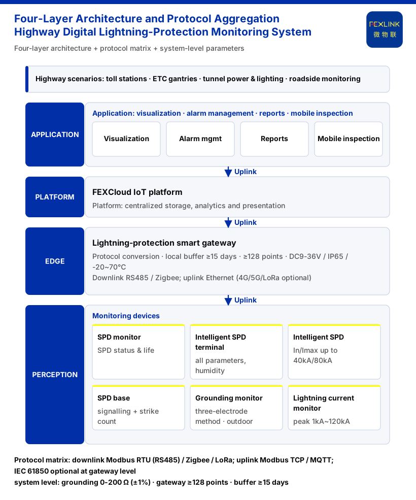
Readable data also needs a path and a carrier. The monitoring system is organised in a four-layer architecture: perception, edge, platform and application. At the perception layer, surge protective device monitors, grounding resistance monitors, lightning-current monitors, the electrical-safety module series, smart meters and sensors complete protocol conversion and local caching through edge-layer devices such as the lightning-protection smart gateway and the intelligent edge-computing gateway, upload to the FEXCloud IoT cloud platform layer, and then, at the application layer, provide visualisation, alarm management, analytics reports and mobile inspection. This path of "edge aggregation, platform centralisation, application presentation" directly addresses scattered, unattended lines.
The transport side is supported by a protocol matrix: device downlinks include Modbus RTU (RS485), Zigbee (Modbus) and LoRa; device uplinks include Modbus TCP / MQTT (Ethernet, 4G); and at gateway level IEC 61850 is optional. Wireless and LoRa offer optional access for long sections and points where cabling is difficult.
System-level reference parameters respond to the practical constraints of outdoor and linear deployment. In the grounding resistance monitoring system, monitoring units cover 0-200 Ω (standard type, ±1%), 0-500 Ω (high-precision type, ±0.5%) and 0.01-200 Ω explosion-proof type (±2%); protection rating is IP65 with an operating temperature of -20~70 ℃; the smart gateway can mount ≥128 points (cascadable), RS485≥4 channels, Ethernet≥2 channels, optional 4G/5G/LoRa, data caching ≥15 days, DC9-36V wide voltage and IP65. Scattered, power- and communication-poor roadside sites are exactly what these indicators cover.
5. What the Upgrade Means in Engineering Terms
The scenario mapping lists "lightning-arrester condition monitoring (retrofit of existing SPDs)" as a standalone combination: surge protective device monitor / full-element SPD monitoring / SPD base. The point is that the upgrade can add a monitoring layer to an existing protection system rather than rebuild it. For grounding-grid monitoring, one may refer to the "substation/traction-substation grounding-grid online monitoring" combination: grounding resistance monitor (one set per point) + lightning-protection smart gateway + FEXCloud.
A dedicated combination for highway electromechanical systems must be determined according to actual site conditions; this article uses the "retrofit of existing SPDs" and grounding-grid monitoring combinations as a capability mapping. The networking topology, construction procedure, quantity basis, sampling and reporting frequency, offline caching and backfill, and alarm work-order rules for this scenario must be determined according to site conditions and relevant specifications, and are not inferred here.
6. Boundaries: What This Article Does Not Claim
First, the driving factors of the move "from traditional to digital" and the three engineering characteristics are this article's analytical framework, not an operating procedure or acceptance basis.
Second, a dedicated networking scheme for highways, determination of lightning-protection levels, equipotential-bonding practice and rectification effects must be determined according to site conditions and the relevant specifications, and this article makes no assertion about them; nor does it give implementations of construction procedures, quantities, sampling and reporting frequency, offline caching and backfill, or alarm work-order rules and evidence formats.
Third, this article does not claim any customer case, certification, compatibility conclusion or handling effect, and does not list models, parameters or standard clauses that cannot be verified.
This article answers only why highway electromechanical systems need digital lightning protection, and what verifiable capability the upgrade can build on.
Conclusion
Highway electromechanical systems need digital lightning protection not because there are too few devices, but because the traditional approach cannot answer whether the line is still effective: SPD degradation, grounding changes and strike events mostly occur between two inspections, while long lines, scattered points, outdoor exposure and delayed on-site troubleshooting magnify the cost of the invisible. The continuity offered by the upgrade is verifiable — surge protective device monitors, intelligent lightning-protection monitoring terminals, intelligent surge protective devices and SPD bases for SPD status and lifetime; grounding resistance monitors for the grounding grid; lightning/transient-current monitors for strike events; aggregated through the lightning-protection smart gateway with the four-layer architecture, protocol matrix and system-level parameters; and mapped under the "lightning-arrester condition monitoring (retrofit of existing SPDs)" and grounding-grid monitoring combinations.