 FEXLINK Research Institute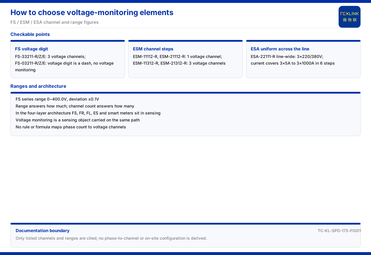
Direct Answer
On the question of how to select voltage-monitoring elements, the information in the product documentation divides into three layers. The first layer is how many voltage channels and what range a specific product can provide. The second is where the voltage channel sits in the monitoring system. The third is whether the documentation gives a rule for choosing the channel count by condition. For the first layer, the FS surge protective device monitor (FS-33211-R) provides 3 voltage channels, while the FS surge protective device monitor (FS-03211-R) in the same series has its voltage position marked as "—", meaning it does not include voltage monitoring; the intelligent lightning-protection monitoring terminal (ESM-11312-R) provides 3 voltage channels, and the intelligent lightning-protection monitoring terminal (ESM-11112-R) provides 1; the ESA all-parameter smart meter (ESA-22111-R) provides 3×220/380V voltage monitoring across the whole series. For the second layer, the general four-layer architecture of the monitoring system places the FS, FR, FL, and ES series monitoring modules and smart meters in the perception layer, and voltage monitoring is one of the perception layer's acquisition objects. For the third layer, the documentation lists only voltage channel counts and ranges and gives no decision rule or formula for choosing the voltage channel count by distribution phase.
Separating these three layers prevents an optional channel count from being misread as a selection rule. This article explains the listed voltage capability, the range definition, and the documentation boundary on that basis.
1. The Voltage Position in the FS Model Rule
The product documentation writes the model rule of the FS surge protective device monitor as a structure of several digit segments, corresponding in turn to voltage channel count, leakage-current channel count, temperature channel count, switching value, and grounding or lightning, followed by the communication suffix; the voltage channel count is an independent position in the model code. Voltage monitoring is therefore not a default configuration of every FS model but one element determined by the model segments.
The model table gives a direct contrast: the FS surge protective device monitor (FS-33211-R/Z/E) has 3 voltage channels, while the FS surge protective device monitor (FS-03211-R/Z/E) has its voltage position marked "—", indicating no voltage monitoring. The two models side by side show that within the same FS series the voltage channel count is selectable by model. The user must read the model segments first to confirm whether a specific model includes voltage monitoring.
2. The Definition of the Voltage Range
On voltage range, the documentation lists two values for the FS series: 0~400.0V and ±0.1V. Range and deviation should be read separately: the range states the lower and upper measurable voltage, while ±0.1V states the order of measurement deviation. This article cites these two values but does not infer the wiring method, phase count, or setting method to which they apply.
It should be emphasized that range answers how large a voltage can be measured while channel count answers how many voltages can be measured; the two answer different questions. When confirming a specific FS model, both the voltage position segment and the range parameter should be checked, not just one of them.
3. The Voltage Channel Distinction of the ESM
The documentation distinguishes the models of the intelligent lightning-protection monitoring terminal by voltage channel count: the intelligent lightning-protection monitoring terminal (ESM-11112-R/21112-R) provides 1 voltage channel, and the intelligent lightning-protection monitoring terminal (ESM-11312-R/21312-R) provides 3 voltage channels. Within the same ESM series, voltage monitoring is likewise stepped by channel count.
This is consistent with the FS treatment: the voltage channel count is a model-level difference item, not a fixed value. Viewed together, the FS and ESM show that voltage monitoring appears as a selectable channel count in both types of lightning-protection monitoring product.
4. Voltage Monitoring of the ESA
The documentation lists the voltage-monitoring definition of the ESA all-parameter smart meter across the whole series as 3×220/380V, covering 6 current specifications from 3×5A to 3×1000A. Voltage and current are the two basic quantities of a meter: voltage is given in the form of a three-phase line voltage, while current covers different load grades with multiple specifications.
Unlike the model-by-model channel selection of the FS and ESM, the ESA voltage monitoring is a uniform 3×220/380V across the series. This difference shows that the configuration logic of voltage monitoring is not the same across product lines, and selection must return to the specific product entry.
5. The Position of Voltage Monitoring in the Architecture
The general four-layer architecture of the monitoring system in the documentation places the FS, FR, FL, and ES series monitoring modules and smart meters in the perception layer, and voltage monitoring is one of the perception layer's acquisition objects. Above the perception layer are the edge layer, platform layer, and application layer, and the voltage quantity converges upward along the same architecture with other acquired quantities.
Making this clear helps explain the role of the voltage element: it is first an acquired quantity, not an analysis conclusion. The perception layer converts the field voltage state into reportable data, and later trend judgment and alarming occur at higher layers.
In the four-layer architecture, the data channel between the perception layer and the platform layer is carried by the edge layer, and the voltage quantity is reported along the same path as other acquired quantities. Voltage monitoring therefore does not require a separate channel design but shares the link with other quantities in the same product line.
6. Putting Channel Count, Range, and Model Back into Selection Order
Combining the preceding information yields a reading supported by the documentation: first, confirm whether the product has voltage monitoring, which is determined by the model segments, for example the FS surge protective device monitor (FS-03211-R) has its voltage position marked "—", meaning no voltage monitoring; second, confirm the channel count, which for the FS and ESM is stepped by model and for the ESA is uniform across the series; third, confirm the range, which for the FS series is 0~400.0V and ±0.1V. The suffix and communication method are chosen after the function is fixed.
This order separates whether it is needed from how much is needed. The documentation guarantees only that each listed value is retrievable; it does not guarantee a formula that derives the channel count directly from the phase count. A selection conclusion should therefore return to the model entry itself rather than rely on inference.
7. The Documentation Boundary of the Selection Basis
On how to choose the voltage channel count, the documentation lists only voltage channel counts and ranges and gives no decision rule or formula for choosing the voltage channel count by distribution phase. It can therefore answer how many channels and what range a model provides, but not how many voltage-monitoring channels a three-phase circuit should have, which would require a decision rule.
This article gives no correspondence between phase count and channel count and does not write any inference as a rule. If the channel count must be determined, the site's count of monitored objects and the product's listed channel counts should be used as inputs and the selection judgment completed outside the documentation.
Scope and Limitations
First, this article restates only what the product documentation lists. The FS model rule and voltage position, the FS voltage range, the ESM voltage channel distinction, and the ESA voltage and current specifications are cited as written.
Second, this article does not infer the installation method, wiring method, protection rating, or parameter setting of the FS, ESM, or ESA, and does not derive any on-site configuration from range and channel count.
Third, the relationship between voltage monitoring and the perception layer is cited as listed in the general four-layer architecture; this article does not extend to layers or devices outside the architecture.
Fourth, this article gives no rule or formula for choosing the voltage channel count by distribution phase, because that decision basis is outside the factual boundary of the product documentation.