 FEXLINK Research Institute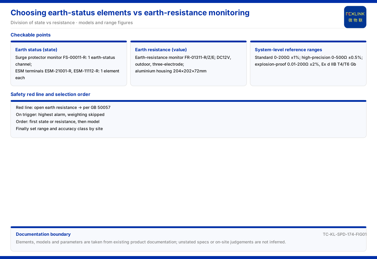
Direct Answer
Selecting a grounding-condition monitoring element starts with separating two distinct objects: grounding status, a state variable describing whether the loop is normally connected or broken, and grounding resistance, a physical quantity describing the resistance of the grounding grid. In the product documentation, the FS surge protective device monitor and the intelligent lightning-protection monitoring terminal both carry a grounding-status element, each rated at 1 channel, whereas the grounding resistance monitor provides grounding-grid resistance measurement by the three-electrode method and offers three reference ranges: 0-200Ω, 0-500Ω, and an explosion-proof variant. If the site only needs to judge whether the grounding loop is normal, choose the former; if it needs to know the grid resistance and judge its trend, choose the latter. The two are not substitutes but a division of labor between a state quantity and a resistance quantity. This article cites only the element positions, models, and parameter definitions in the product documentation and does not infer specifications for unlisted models.
1. First Separate "Grounding Status" from "Grounding Resistance"
"Grounding" is often treated as one broad term in lightning-protection monitoring, but it corresponds to two different kinds of information. Grounding status is a state quantity that answers whether the loop is normal or has been broken or opened. Grounding resistance is a resistance quantity that answers how large the grid resistance is and whether it changes with season or corrosion. The product documentation places these two kinds of information under different product entries: the FS surge protective device monitor and the intelligent lightning-protection monitoring terminal both provide a grounding-status element, while the grounding resistance monitor provides grounding-grid resistance measurement. Once the objects are separated, parameter reading does not blur: "1-channel grounding" points to a state element, while "three-electrode method" or an "Ω range" points to the grounding resistance monitor. Many selection disagreements arise from reading a state quantity as a resistance quantity, or demanding that a status-only module deliver a resistance value.
2. Status Only: The SPD Monitor and the Intelligent Monitoring Terminal
If the site only needs to confirm the state of the grounding loop, the FS surge protective device monitor (FS-00011-R) is one selectable product in the documentation. Its model rule encodes the voltage channel count, leakage-current channel count, temperature channel count, switching value, and grounding/lightning element position by digit, and it includes a grounding/lightning element position; in the model table, this model has 1 channel of grounding status. This means grounding status sits alongside voltage, leakage current, temperature, and switching value as an element inside the same monitor, not as a separate device.
Another option is the intelligent lightning-protection monitoring terminal (ESM-21001-R, ESM-11112-R). The product documentation records that every model of this family contains a grounding-status element, also at 1 channel. A single terminal therefore covers SPD status, leakage current, lightning strike counting, and grounding status, and grounding status is only one of those positions. If the site needs only the judgment "is the loop normal," a family carrying a state element can satisfy it; the documentation gives no decision threshold for the grounding-status element, so this article cites only the element position and channel count.
3. Resistance Needed: The Grounding Resistance Monitor
If what is needed is grid resistance rather than status, the grounding resistance monitor should be chosen. Its model rule encodes signal acquisition, detection principle, installation method, and power supply by digit; the detection-principle position includes two values, the loop method and the three-point method, and the signal-acquisition position is marked as grounding-grid resistance. This encoding shows that the product definition of the grounding resistance monitor is built around resistance measurement, which differs in object from products that output only a state element.
The models recorded as available are the grounding resistance monitor (FR-01311-R), (FR-01311-Z), and (FR-01311-E). All three use DC12V supply, outdoor installation, and three-electrode measurement, with an aluminum housing and dimensions of 204 by 202 by 72 mm. The boundary to hold here is that the three models differ in the communication suffix of the model code, while measurement principle and installation method are identical; the documentation does not give a per-unit resistance accuracy value, and the accuracy definition belongs to the system-level reference parameters. Seeing "three-electrode method" should be assigned to the grounding resistance monitor, while seeing "1-channel grounding" should be assigned to the state element; the two cannot be substituted for each other.
4. System-Level Reference Parameters and Range Steps
At the system level, the documentation gives reference parameters for the monitoring unit of the grounding resistance monitoring system: the standard type has a range of 0-200Ω at ±1% accuracy; the high-precision type has a range of 0-500Ω at ±0.5% accuracy; and the explosion-proof type has a range of 0.01-200Ω at ±2% accuracy, with an explosion-proof rating of Ex d IIB T4/T6 Gb. These three steps indicate that resistance monitoring has three orientations — standard, high-precision, and explosion-proof: use the standard type for an ordinary grid, the high-precision type when accuracy requirements are higher, and the explosion-proof type in locations such as tank farms that require explosion protection.
Select the occasion first, then fix the range and accuracy step, rather than defaulting to the largest range. These three steps belong to the system-level monitoring unit and are not equivalent to the per-unit parameters of any single instrument above; keep the system-level definition separate from the model-table definition, and avoid writing a system range directly as one model's indicator.
5. Grounding Abnormality and the Safety Red Line
In the safety red-line guard mechanism of the product documentation, one rule targets an abnormal open circuit of grounding resistance, with GB 50057 as its standard basis. The mechanism states that a safety red line cannot be bypassed, that no person can raise its threshold, and that once triggered it outputs the highest-level alarm and skips the weighted calculation. A grounding abnormality is therefore not an ordinary alarm but sits at the red-line level of mandatory handling.
This article cites only the existence of the red line, its non-bypassable property, its standard basis, and the handling after triggering; it does not restate the specific trigger value or infer a site decision. For the site, the red line elevates "abnormal open circuit of grounding resistance" from an optional analysis item to one that must be answered; how to confirm an open circuit and by what means to re-test it are not expanded in the documentation, and this article does not supplement them.
6. Selection Order in Typical Scenarios
In typical application scenarios and selection cross-references, the documentation gives two combinations. For online monitoring of the grounding grid of substations and traction substations, it recommends the grounding resistance monitor (1 set per point) together with the lightning-protection smart gateway and the FEXCloud platform; for lightning-arrester condition monitoring in an existing SPD retrofit, it recommends the FS surge protective device monitor, the intelligent lightning-protection monitoring terminal, and the SPD lightning-protection base. The former takes grid resistance as its object and is configured by point; the latter takes the existing SPD structure and is configured by element coverage.
From this a selection order can be arranged: first, confirm whether status or resistance is required; second, choose the FS surge protective device monitor or the intelligent lightning-protection monitoring terminal for status, and the grounding resistance monitor for resistance; third, fix the range and accuracy step by occasion; fourth, bring grounding abnormality into the red-line handling definition. Keeping to this order prevents the grounding-status element and grounding-resistance monitoring from being conflated.
Scope and Limitations
First, this article restates only what the product documentation lists, and its factual boundary is limited to the grounding-status element, the models and parameters of the grounding resistance monitor, and the system-level reference parameters and safety red-line records.
Second, the 1-channel grounding status of the FS surge protective device monitor (FS-00011-R), and the grounding-status element of the intelligent lightning-protection monitoring terminal (ESM-21001-R, ESM-11112-R), are cited as listed in the model table; this article does not supplement grounding configurations of unlisted models and does not give a status decision threshold.
Third, the DC12V supply, outdoor installation, three-electrode method, and aluminum housing dimensions of the grounding resistance monitor (FR-01311-R, FR-01311-Z, FR-01311-E) are cited as listed in the model table; this article does not supplement per-unit accuracy and range.
Fourth, the 0-200Ω, 0-500Ω, and explosion-proof 0.01-200Ω ranges of the grounding resistance monitoring system monitoring unit and their respective accuracies are cited as listed in the system-level reference parameters; this article does not infer a concrete project selection from them.
Fifth, the abnormal open circuit of grounding resistance in the safety red line and the GB 50057 basis are cited as listed; this article does not restate the specific trigger value and does not infer a site decision.
Sixth, the typical scenario combinations are cited as listed in the selection cross-reference; this article does not expand them into a concrete project plan, and the latest product documentation and formal documents prevail in practice.