 FEXLINK Research Institute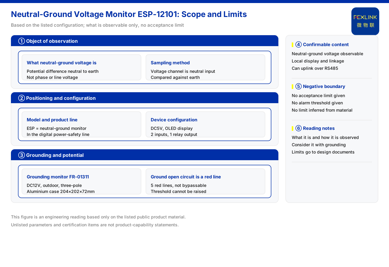
Direct answer
Neutral-to-ground voltage is the potential difference between the neutral conductor and ground. In the current product documentation, the device used to observe this difference is the neutral-to-ground voltage monitor (ESP-12101-R). It takes a neutral-line input, is powered by DC5V, carries an OLED display, provides two digital inputs and one relay output, and communicates over RS485. The documentation assigns this product to the digital power-usage and electrical-safety monitoring product line and records it in the model quick reference as the ESP neutral-to-ground voltage monitor. Its importance comes from the typical-application section, where data-centre neutral-to-ground voltage and distribution monitoring are listed as a recommended combination, while the grounding resistance monitor and the non-bypassable safety red line for an abnormal open circuit of the grounding resistance are placed in the same grounding-and-potential category. It should be noted that the documentation gives neither an acceptance limit nor an alarm threshold for neutral-to-ground voltage; this article therefore states only that it is an observable potential difference and how it is monitored, and does not conclude what range is acceptable.
1. What the neutral-to-ground voltage observes
The name points at the potential difference between the neutral conductor and ground. In the parameters of the neutral-to-ground voltage monitor, the current product documentation records the voltage channel as a neutral-line input, which means the device samples the potential on the neutral side and compares it with ground, thereby obtaining the difference between neutral and ground. Unlike quantities such as phase voltage and line voltage, which describe the supply voltage itself, neutral-to-ground voltage concerns the relation between reference potentials, so it is closer to a potential-health indicator. The documentation does not develop the causes of this difference within a distribution system, and this article likewise does not infer them; it defines only what is measured.
2. Product positioning and line assignment
To judge whether an indicator matters, one first looks at where the documentation places it. The model quick reference records ESP as the neutral-to-ground voltage monitor, and the product-line overview assigns the neutral-to-ground voltage monitor to the digital power-usage and electrical-safety monitoring product line. This placement shows that neutral-to-ground voltage monitoring is not an accessory of general electrical measurement but is listed as a product category of its own. The fact that the device is given a separate entry reflects that the indicator needs to be observed specifically in electrical-safety monitoring rather than recorded incidentally.
3. Display, input/output, and communication
In device form, the neutral-to-ground voltage monitor (ESP-12101-R) is powered by DC5V, carries an OLED display, provides two digital inputs and one relay output, and communicates over RS485. These features describe how it works: the OLED display supports on-site reading of the potential difference; the two digital inputs can accept external status signals; the one relay output can drive local interlocking; and RS485 can send data upward to a higher-level system. Placing local display, local interlocking, and communication uplink on the same device means neutral-to-ground voltage can be seen directly on site and also brought into centralised monitoring.
4. Grounding and potential monitoring belong to one category
Neutral-to-ground voltage cannot be viewed in isolation because the documentation places it in the same category as grounding state. The grounding resistance monitor listed in the current product documentation (FR-01311-R, also offered as FR-01311-Z and FR-01311-E) is powered by DC12V, installed outdoors, measures by the three-electrode method, communicates over RS485, Zigbee, and Ethernet respectively, and uses an aluminium housing measuring 204 × 202 × 72 mm. The documentation also lists an abnormal open circuit of the grounding resistance as one of the non-bypassable safety red lines: there are five such red lines, none of which can be bypassed, and no one can raise their thresholds. Grounding resistance reflects the state of the grounding body itself, while neutral-to-ground voltage reflects the potential relation; together they form the grounding-and-potential monitoring surface. Only by placing neutral-to-ground voltage monitoring alongside grounding monitoring can the state of this category be observed relatively completely.
5. Typical scenarios show its use
In its typical-application section, the current product documentation lists data-centre neutral-to-ground voltage and distribution monitoring as a recommended combination, with a recommended configuration of the neutral-to-ground voltage monitor (ESP-12101-R), the all-parameter smart meter, and the edge-computing gateway. The point of this combination is that it brings neutral-to-ground voltage observation together with distribution parameters and data uplink: neutral-to-ground voltage is observed by a dedicated device, distribution information is measured by the meter, and the data is then aggregated through the edge-computing gateway. Using a data centre as the example, the documentation indicates that this indicator deserves particular attention in sites that are sensitive to potential and demanding on supply quality. The documentation gives no limit requirement for this scenario, so only the correspondence between scenario and use is stated here.
6. Acceptance limits are outside the documented scope
A common follow-up question is how high a neutral-to-ground voltage may be before it is unacceptable. The current product documentation gives neither an acceptance limit nor an alarm threshold for neutral-to-ground voltage. This means the article cannot conclude that "anything below a certain number of volts is normal", nor can it declare a particular field reading to be out of limit. What can be confirmed is only this: neutral-to-ground voltage is a potential-difference indicator observable by a dedicated device; that device has local display, local interlocking, and communication-uplink capabilities; and the documentation places it together with grounding monitoring in sites sensitive to grounding and potential. Limit decisions should rest on engineering design documents and the relevant standards, not on inference from the current product documentation.
7. A verifiable check sequence
For ease of review, the check can be reduced to four steps. First, confirm that the monitored object is the potential difference between neutral and ground, not phase voltage or line voltage. Second, confirm that the monitoring device has the necessary local display and interlocking capability and can uplink over RS485. Third, consider neutral-to-ground voltage monitoring together with grounding resistance monitoring, and confirm whether the grounding baseline is already observed. Fourth, check whether there is a need to cite an acceptance range or alarm threshold for neutral-to-ground voltage; if so, it should be marked explicitly as a matter not listed in the current documentation and left to design documents and standards. Following this order answers what neutral-to-ground voltage is and how it is observed, rather than what value makes it acceptable.
Scope and limitations
First, this article restates only what the current product documentation lists, and its factual boundary is limited to the voltage sampling method, power supply, display, input/output and communication of the neutral-to-ground voltage monitor, its product-line assignment and model quick-reference positioning, the basic configuration of the grounding resistance monitor, the nature of the grounding-resistance abnormal-open-circuit red line, the typical-application combination, and the fact that acceptance limits and alarm thresholds are not listed.
Second, acceptance limits and alarm thresholds for neutral-to-ground voltage are matters not listed in the documentation, and this article makes no numerical judgement or inference about them.
Third, the display, input/output, and communication of the neutral-to-ground voltage monitor are cited as listed, and this article draws no conclusion about its measurement accuracy, sampling period, or installation details.
Fourth, the three-electrode method, power supply, and communication of the grounding resistance monitor are cited as listed, and this article makes no extended judgement about its measurement conditions.
Fifth, the typical-application combination is used only to explain the direction of use and configuration, and no commitment is made about the monitoring outcome of any specific project.
Sixth, this article does not constitute a commitment regarding the selection result or field performance of any specific project; the latest product documentation and project scheme prevail.