 微物联研究院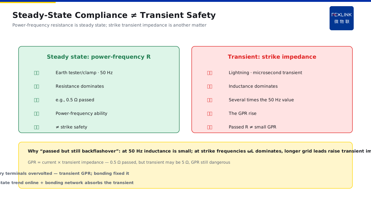
Direct Answer
The earthing is done well and the earth resistance meets the code — so why does a dangerous voltage still appear between the terminals of nearby equipment the moment lightning strikes? The answer: lightning current is a transient, microsecond-scale surge of tens of kiloamperes; as it enters the earth it produces an instantaneous drop across the earth-grid leads and grid impedance, lifting the whole grid relative to a remote zero-potential point (ground potential rise, GPR). If the different metal parts are not bonded, the raised potential difference discharges across the equipment insulation as backflashover — meeting the steady-state earth resistance does not mean there is no transient backflashover; bonding is the key.
At a substation the earth resistance met the code (0.5 Ω level), yet after a strike the secondary terminals saw overvoltage and some modules failed. Investigation: at the instant the lightning current entered the earth, the whole grid potential rose; the potential difference between the secondary equipment and the primary equipment, and between different grid nodes, was not bonded, so the backflashover voltage landed on the terminals. After strengthening the bonding, no recurrence. The key distinction: steady-state earth resistance governs "power-frequency earthing"; transient GPR governs "the strike instant" — when the whole grid rises, backflashover appears wherever there is no bonding.
Why:
- GPR generation: ground potential rise ≈ lightning current × transient grid impedance (large current × impedance = instantaneous high potential);
- Transient ≠ steady state: a strike is a microsecond-scale large current; the transient impedance is not the power-frequency earth resistance;
- Where the potential difference appears: between different metal parts (enclosures, cable screens, different grid nodes) where bonding is missing;
- What bonding does: it "shorts" the points to one potential, so the backflashover voltage disappears.
Key insight: "Earth-resistance compliance governs the steady state; bonding governs the transient — when GPR rises, backflashover strikes wherever there is no bonding."
At a factory, after a thunderstorm, arcing marks appeared between a device's enclosure and its power terminals; the earth resistance still passed. Investigation showed the enclosure earth and the power earth each sat on an isolated section of the grid, and the strike raised the two points to a potential difference applied directly across the device. After tying the enclosure, power earth and cable screens into one bonding network, no recurrence. Lesson: "qualified" earth resistance is only the baseline; the potential rise at the strike instant must be absorbed by the bonding network.
1. How GPR Is Produced: Large Current × Grid Impedance
Step one: what happens on the ground when lightning current enters.
The essence of GPR:
- Lightning current I (tens of kA) enters the earth via down-conductors and the grid;
- The current produces a drop across the earthing leads and grid resistance/inductance;
- The grid potential rises as a whole relative to a "remote zero-potential point";
- The rise = lightning current × transient earthing impedance (GPR).
Why "rises as a whole":
- The grid is a conductive network; the injection point has the highest potential;
- The whole grid "floats up" with the current (relative to remote earth);
- The farther from the grid, the closer the reference potential is to zero;
- A device earth point is "high potential" relative to remote earth.
A sense of magnitude:
- Lightning current 30 kA, transient impedance 5 Ω → GPR can reach the 150 kV level;
- Even at 1 Ω, 30 kA gives 30 kV;
- That difference is enough to break down equipment insulation;
- GPR is the "source voltage" of strike backflashover.
Key insight: "GPR = large current × grid impedance — with tens of kA, even a few ohms lifts the potential to a dangerous level."
2. Transient Earthing Impedance ≠ Steady-State Earth Resistance
Step two: why "resistance compliance" is not enough.
Steady-state earth resistance:
- Earth resistance measured at power frequency (50 Hz);
- Measured with an earth tester/clamp meter;
- Reflects the ability to take power-frequency current;
- Meeting it ≠ lightning safety.
Transient earthing impedance:
- Lightning current is a microsecond transient;
- Under high-frequency components, grid inductance dominates;
- The transient impedance can be several times the power-frequency resistance;
- Large current also causes sparking effects around electrodes (a complex transient phenomenon).
Why they differ:
- At 50 Hz the inductive impedance is small and resistance dominates;
- At strike frequencies the reactance ωL is significant;
- The longer the grid lead, the higher the transient impedance;
- So "0.5 Ω compliance" does not mean a small GPR.
Key insight: "Steady-state resistance is a power-frequency concept; transient impedance is a strike concept — judging lightning safety by a power-frequency pass is a common blind spot."
3. Where the Potential Difference Appears
Step three: where the backflashover hits.
The "two points" of backflashover:
- The device enclosure (earth point A) and its internal terminals (earth point B);
- Between different device enclosures;
- Between the enclosure and the cable screen/signal reference;
- Between primary and secondary equipment.
Where bonding is missing:
- Metal parts not shorted by bonding;
- Connections between isolated grid sections;
- Both ends of long cable runs;
- Interfaces (network/signal cables crossing regions).
Backflashover consequences:
- Dangerous voltage between terminals;
- Insulation breakdown, module damage;
- Secondary-system mal-operation/non-operation;
- Electric shock to personnel touching the enclosure.
Key insight: "Backflashover is not 'bad earthing' but 'two points at different potentials' — the missing-bonding spot is where it strikes."
4. How Bonding "Shorts Out" the Potential Difference
Step four: the solution to GPR.
Bonding:
- Connect all metal parts to one potential reference;
- Interconnect enclosures, cabinets, cable screens, structural steel;
- Use short, thick bonding conductors (low impedance);
- At the strike instant all points rise together → the difference disappears.
Why it works:
- Potential difference = the difference of the two rises;
- After bonding the two points rise simultaneously, difference ≈ 0;
- The device terminals no longer carry the backflashover voltage;
- The current distributes along low-impedance paths instead of "pushing" the insulation.
Engineering points:
- Bonding conductors short, thick, straight (low inductance);
- Include everything in one bonding network (MEB/LEB concepts);
- Coordinate with GPR analysis (overall potential-rise assessment);
- Follow the code for secondary-system screen earthing (single/multiple point).
Key insight: "Bonding is not 'earthing well' but 'making all points share one potential' — when GPR rises as a whole, synchronous rise means no backflashover."
5. Why a Larger Grid with Better Equalization Lowers the Backflashover Risk
Step five: how grid design affects GPR.
Grid area and GPR:
- The larger the grid, the lower the earthing impedance;
- Large current spreads over a wide area, gentler potential gradient;
- The GPR amplitude decreases;
- The backflashover risk drops accordingly.
Equalization effect:
- Dense grid meshes → uniform surface potential;
- Small potential differences between equipment earth points;
- Multi-point down-conductor/ground connections → current dispersal;
- Equalization reduces the "two-point potential difference" as a whole.
Engineering combination:
- Increase the grid area and mesh density;
- Interconnect down-conductors and grid at multiple points;
- Cover all metal with the bonding network;
- Track the grid state online with the FR Earth-Resistance Monitor.
Key insight: "Larger grid, denser meshes, more complete bonding — smaller GPR, flatter potential differences, lower backflashover risk — that is the design combination."
6. Product Implementation: Intelligent Lightning-Protection Online Monitoring
WeiWuLian products manage GPR/backflashover risk:
- FR Earth-Resistance Monitor: tracks the grid state online (steady-state resistance/trend);
- Monitoring platform: earth-resistance drift warnings (grid corrosion/disconnection);
- Design support: GPR assessment + bonding-retrofit effect verification;
- Strike correlation: correlate strike events with grid state.
The design principle in one sentence: "Steady-state monitoring as the baseline, bonding network absorbing the transient — GPR risk visible and preventable."
7. Common Misjudgments
- "Earth-resistance compliance means safe": ignoring transient GPR. Result: backflashover still occurs. Correct: assess steady state and transient separately.
- Only a large grid, no bonding: the point potentials still differ. Result: backflashover still strikes. Correct: full bonding coverage.
- Over-long bonding conductors: a high-impedance short is ineffective. Result: the difference is not removed. Correct: short, thick, straight conductors.
- Isolated grids not interconnected: large difference between two points. Result: cross-grid equipment damaged. Correct: multi-point grid interconnection.
- Grid state unmonitored: corrosion/disconnection unknown. Result: GPR quietly worsens. Correct: FR online trend monitoring.
Scope and Limitations
This article explains the mechanism of ground potential rise (GPR) when lightning current enters the earth, the difference between transient impedance and steady-state resistance, the source of the backflashover potential difference, and the bonding solution, applicable to lightning-protection earthing design and backflashover protection. The quantitative GPR calculation and bonding design must follow GB/T 21714 and GB 50057-2010, covering grid impedance, lightning-current parameters and equipment insulation withstand, completed by professional design. All cases are anonymized (a substation, a factory) and do not refer to any specific customer.