 微物联研究院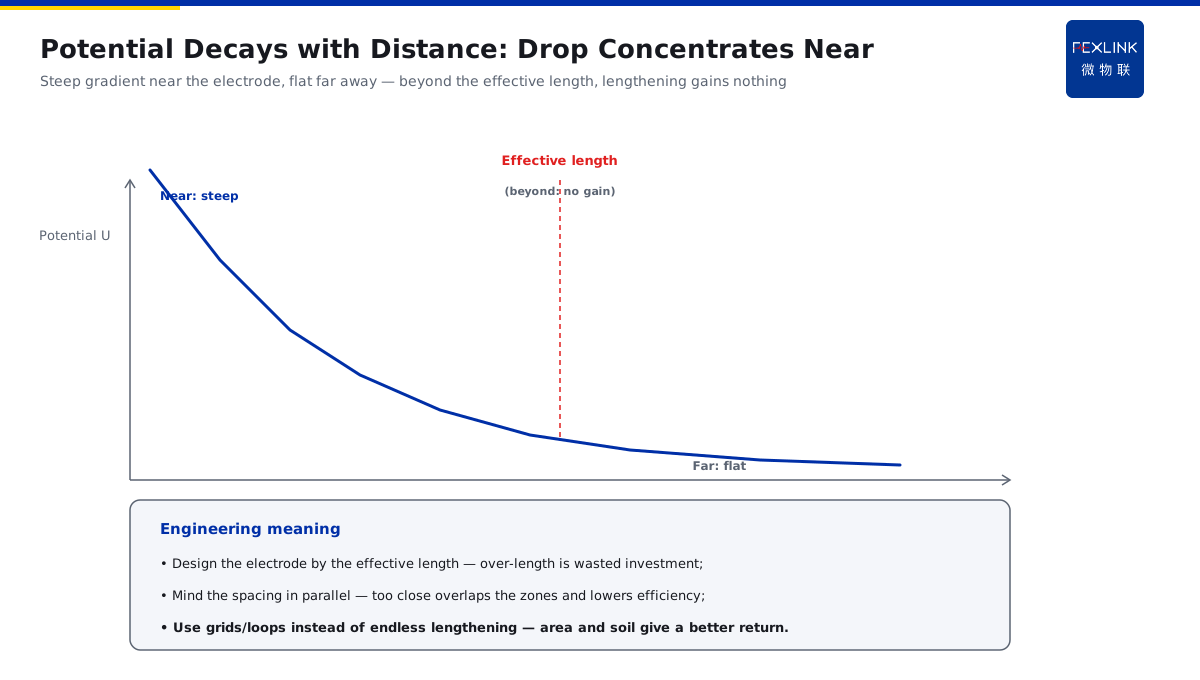
Direct Answer
Once an earth electrode is buried, how does lightning current spread, and why does the potential drop far away? The answer: after lightning current is injected into the soil through the electrode, it spreads outward from around the electrode; the current density falls with distance, and the soil voltage drop concentrates in the region near the electrode — therefore the earth resistance is mainly determined by the current-spreading conditions of the soil near the electrode. That is why reducing resistance means enlarging the spreading area, backfilling low-resistivity soil or drilling deep wells, not endlessly lengthening a single electrode.
At a factory, a single vertical electrode measured a qualified earth resistance, yet nearby equipment still misbehaved after strikes; re-inspection found the soil around the electrode was compacted and dry, with poor spreading conditions. After backfilling low-resistivity soil around the electrode and enlarging the spreading area, the earth resistance dropped markedly and the equipment anomalies disappeared. The key distinction: earth resistance is not the resistance of the electrode itself but the resistance of the soil-spreading conditions near it — the drop concentrates near the electrode, and the spreading area sets the room for reduction.
Why:
- Spreading process: current diffuses from the electrode in an approximate hemisphere; the current density falls with distance;
- Concentrated drop: near the electrode the current density and the drop are greatest; far away the drop tends to zero;
- Effective-length limit: an over-long electrode contributes little at the far end and gains nothing;
- Basis for reduction: enlarging the area, backfilling soil, deep wells and resistance-reducing agents all improve the spreading conditions near the electrode.
Key insight: "Earth resistance is set mainly by the soil near the electrode — reduce resistance by enlarging the spreading area and improving the spreading conditions, not by lengthening one electrode."
At an airport, the aid-to-navigation lamp circuit earthing used multiple parallel vertical electrodes yet remained unsatisfactory. The design was changed to a combination of "vertical electrodes + a horizontal grid + low-resistivity backfill"; after the spreading area was enlarged the earth resistance met the code and the strike-related fault rate fell. Lesson: seeing resistance reduction as "driving a few more rods" is one-sided — the spreading area and soil conditions are what decide.
1. The Spreading Process: Current Diffuses from the Electrode in a Hemisphere
Step one: where does the current go once it enters the soil.
The geometry of spreading:
- Current enters the soil from the electrode surface;
- It diffuses outward with the electrode at the centre;
- The equipotential surfaces are approximately hemispherical;
- The current density falls with distance.
The current-density change:
- The density is highest at the electrode surface;
- It decays roughly with the inverse square of distance;
- Far away the density tends to zero;
- The soil participating in spreading is limited in extent.
The potential distribution:
- Near the electrode the potential gradient is steep;
- Far away the potential is flat and tends to zero;
- "The drop concentrates in the near region" is the core idea;
- This is the "spreading zone" concept.
Key insight: "Current spreads hemispherically from the electrode and the density decays with distance — spreading happens mainly near the electrode; the far field contributes little."
2. Why the Drop Concentrates near the Electrode
Step two: why "a small earth resistance" depends on the near region.
Drop = current × resistance:
- Near the electrode the current density is high;
- At the same soil resistivity the near-region drop is large;
- Far away the density and the drop are small;
- The total drop is dominated by the near region.
Composition of the earth resistance:
- Earth resistance ≈ the near-region soil spreading resistance;
- The electrode's own resistance is negligible;
- The electrode–soil transition resistance also counts;
- The far-region soil contributes little.
Engineering meaning:
- High soil resistivity → high earth resistance;
- Improving the soil near the electrode gives the largest effect;
- Electrodes too close together → overlapping spreading zones;
- Reduce resistance by improving the "near region" first.
Key insight: "The drop concentrates near the electrode — improving the spreading conditions of the near-region soil works better than lengthening the electrode."
3. The Effective Length of an Earth Electrode Has an Upper Limit
Step three: why "lengthening without end" does not help.
The physics of effective length:
- Current spreads along/down the electrode;
- At the far end the spreading current is already small;
- Beyond the effective length the contribution tends to zero;
- Adding length does not reduce the resistance.
A sense of magnitude:
- A single vertical electrode has a finite effective length (related to soil resistivity);
- Horizontal electrodes also have an effective length;
- Over-long investment is wasted;
- Better to use the same material for spreading area.
Engineering meaning:
- Design the electrode length by the effective length;
- Mind the spacing in multi-electrode parallel connections (avoid shielding);
- Too-close spacing → overlapping spreading zones → lower efficiency;
- Use grids/loops instead of endless lengthening.
Key insight: "The electrode's effective length has an upper limit — lengthening gains nothing; the material is better spent on area and soil."
4. The Physical Basis of Resistance-Reduction Methods: Area, Soil, Deep Wells, Agents
Step four: every measure improves the "near-region spreading".
Enlarging the spreading area:
- A horizontal grid/loop extends the spreading range;
- More injection points, lower density;
- Multi-electrode parallel (with enough spacing);
- Directly lowers the near-region drop.
Backfilling low-resistivity soil:
- Replace the soil around the electrode;
- Improves the electrode–soil contact;
- The near-region drop falls significantly;
- Simple construction, stable effect.
Drilling deep wells:
- Reach deep low-resistivity soil/groundwater layers;
- Bring the spreading to a low-resistivity depth;
- Suited to high-resistivity surface sites;
- Deep-well earth electrodes.
Resistance-reducing agents / modules:
- Lower the effective resistivity near the electrode;
- Increase the effective electrode radius;
- Improve the contact (lower transition resistance);
- Mind long-term stability and environmental requirements.
Key insight: "Area lowers density, backfill lowers the near-region resistivity, deep wells find low-resistivity layers, agents enlarge the effective radius — all four improve the spreading conditions."
5. Why Grid Equalization Matters More than a Single Small Resistance
Step five: the engineering landing point of the spreading concept.
The limitation of a single small resistance:
- However small a single point is, its spreading zone is limited;
- The potential gradient can still be steep (a local high drop);
- Potential differences between equipment still exist;
- Equalization is not solved.
The advantage of grid equalization:
- Multi-point injection, dispersed current;
- Uniform surface-potential distribution;
- Small potential differences between equipment earth points;
- Combined with bonding it lowers backflashover risk (connecting to KD-0173).
Engineering combination:
- A large grid + dense meshes (equalization);
- Multi-point earthing (current dispersal);
- A bonding network (removing potential differences);
- FR Earth-Resistance Monitor tracking the state online.
Key insight: "Grid equalization makes the potential distribution flat — more than a single small resistance, it lowers the potential differences between equipment and the backflashover risk."
6. Product Implementation: Intelligent Lightning-Protection Online Monitoring
WeiWuLian products manage the spreading state:
- FR Earth-Resistance Monitor: tracks the earth-resistance trend online (warnings when the spreading conditions degrade);
- Monitoring platform: recognises changes in the electrode–soil contact state;
- Retrofit verification: before/after resistance comparison for area/soil/deep-well retrofits;
- Design support: unified planning of grid equalization + bonding.
The design principle in one sentence: "The spreading area sets the room for reduction, equalization sets the safety margin — FR monitoring makes changes in the spreading conditions visible."
7. Common Misjudgments
- "Lengthen one electrode without end to reduce resistance": beyond the effective length it gains nothing. Result: wasted investment. Correct: enlarge the area / backfill soil.
- "A few more rods are enough": too-close spacing overlaps the spreading zones. Result: low parallel efficiency. Correct: design by effective length and spacing.
- Looking only at the single-point resistance: ignoring equalization. Result: potential differences remain. Correct: grid equalization + bonding.
- Ignoring the near-region soil: compacted/high-resistivity soil. Result: the resistance stays high. Correct: backfill low-resistivity soil.
- No monitoring after reduction: soil changes are unknown. Result: the resistance rises again. Correct: FR tracks the trend online.
Scope and Limitations
This article explains the physical process of electrode current spreading (hemispherical diffusion, near-region concentrated drop), the effective-length limit, the physical basis of resistance-reduction methods (area/soil/deep wells/agents), and the value of grid equalization, applicable to earthing design and resistance-reduction retrofits. Quantitative calculation must follow GB 50057-2010 and GB/T 21714, combined with soil resistivity and electrode layout, completed by professional design. All cases are anonymized (a factory, an airport) and do not refer to any specific customer.