 微物联研究院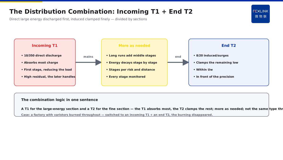
Direct Answer
The incoming line uses a spark-gap type and the end uses a varistor type — what does each class of SPD handle and how should they be combined? The answer: the voltage-switching type (T1, spark-gap class) has a large discharge capacity and can discharge the large charge of a direct strike (the 10/350 class), suitable for the incoming line to take the large energy; the voltage-limiting type (T2, MOV class) has a low residual voltage and smooth clamping, suitable for protecting precision equipment at the end; the reasonable combination is a T1 at the incoming line to discharge the large energy and a T2 at the later stage for fine clamping — not the same type throughout.
A factory originally installed varistor-type SPDs throughout; the large lightning current at the incoming line repeatedly burned the varistors. After switching to a T1 (spark gap) at the incoming line to discharge the large energy and a T2 (varistor) at the end for fine clamping, the burning disappeared and the end equipment was protected. The key distinction: the two classes of SPD are a division of labor, not competition — the T1 handles "discharging the large energy" (incoming line, direct strikes), the T2 handles "fine clamping" (end, induced strikes); the combination logic is a T1 for the large-energy section and a T2 for the fine section, not the same type throughout.
Why:
- The switching type (T1): large discharge capacity, discharging the 10/350 large charge, the incoming line taking the large energy;
- The limiting type (T2): low residual voltage, smooth clamping, protecting precision equipment at the end;
- The combination logic: a T1 at the incoming line discharging the large energy, a T2 at the later stage for fine clamping;
- The inter-stage coordination: attention to decoupling and spacing between the two (relating to KD-0169).
Key insight: "The T1 and the T2 are a division of labor, not competition — the T1 discharges the large energy (incoming line, direct strikes), the T2 clamps finely (end, induced strikes); the combination is a T1 for the large-energy section and a T2 for the fine section, not the same type throughout."
A data center installed only a T1 at the incoming line, and the end equipment was still damaged by induced strikes — missing the T2 fine clamping, the residual voltage was high. After adding the end T2 the problem was solved. Lesson: a T1 only leaves "the energy discharged but the residual voltage high", a T2 only leaves "good clamping but cannot take the large energy" — the two sections in division are complete.
Overview: run "characteristic comparison → waveform positioning → combination logic → inter-stage coordination" as one clear decision. The most common uncertainty in SPD selection is "what goes at the incoming line and what at the end". The answer comes from the characteristic division of the two classes: the switching type (T1) is like a "large water gate", with a large discharge capacity, specialized in discharging the large charge of a direct strike (the 10/350 waveform); the limiting type (T2) is like a "fine stabilizing valve", with a low residual voltage, clamping induced strikes/operating overvoltages within the equipment's withstand range (the 8/20 waveform). The reasonable practice in a distribution system is a T1 at the incoming line taking the large energy and a T2 at the later stage for fine clamping, in two sections. The five steps below expand: the characteristics and action of the switching type, the characteristics and clamping of the limiting type, the waveform and discharge positioning of the two, the combination logic of the incoming T1 + the end T2, and the inter-stage coordination notes.
Why the spark gap is "large discharge capacity, high residual voltage": when the spark gap conducts, it is an approximate short-circuit spark discharge — after the gap is broken down, the impedance is extremely low, the large current discharges freely, so the discharge capacity can be made very large (it can take the 10/350 direct-strike waveform); but precisely because it discharges only after conduction, the voltage at the action moment has an "ignition voltage", and the residual voltage is relatively high. This is not a defect but a division of labor: it takes the "large energy away", and the fine residual voltage is left to the later T2. The gap characteristic = the large water gate — near-short after breakdown, huge discharge capacity, but the residual voltage relatively high; the large energy to it, the fine clamping to the later T2.
1. The Switching Type (T1): Discharging the Large Energy
Step one: what the T1 handles.
The action method:
- Spark-gap/switching structure;
- Conducting only when the voltage exceeds the ignition voltage;
- Approximate short-circuit discharging after conducting;
- Spark-discharge characteristic.
The characteristic parameters:
- Large discharge capacity (the 10/350 class);
- Can discharge the large charge of a direct strike;
- Relatively high residual voltage;
- The "large-energy" role.
The applicable position:
- The incoming line / main distribution;
- The energy entrance of direct or nearby strikes;
- The first-stage discharge;
- "Reducing the load" for the later stage.
Key insight: "The T1 is like a large water gate — large discharge capacity, discharging the 10/350 direct-strike large charge, relatively high residual voltage; at the incoming first stage to discharge, reducing the load for the later stage."
2. The Limiting Type (T2): Fine Clamping
Step two: what the T2 handles.
The action method:
- Varistor (MOV) structure;
- Conducting when the voltage exceeds the action voltage;
- Continuous clamping with the voltage;
- Nonlinear volt-ampere characteristic.
The characteristic parameters:
- Low residual voltage;
- Smooth and continuous clamping;
- Fast response;
- The "fine protection" role.
The applicable position:
- The end / in front of the equipment;
- Protecting precision equipment;
- Clamping the surge within the equipment's withstand (relating to Uw);
- The "fine clamping" role.
Why the varistor is "low residual voltage, smooth clamping": the MOV is a nonlinear resistor whose conduction deepens as the voltage rises — once the voltage exceeds the action threshold, its impedance falls continuously with the voltage, "clamping" the voltage in a range, without first accumulating to the ignition voltage like a gap and then suddenly conducting. So the residual voltage is low and the clamping is continuous and smooth, suitable for placing in front of the equipment to press the surge within the equipment's impulse withstand voltage (Uw). The cost is that the discharge capacity is inferior to the T1 and cannot take the direct-strike large charge — which is exactly why it comes after the T1. The MOV characteristic = the fine stabilizing valve — continuous clamping with the voltage, low residual voltage, but the discharge inferior to the T1; at the end pressing the surge within Uw, after the T1.
Key insight: "The T2 is like a fine stabilizing valve — the MOV clamps continuously, low residual voltage, fast response; at the end protecting precision equipment, clamping the surge within the equipment's withstand."
3. The Waveform and Discharge Positioning of the Two
Step three: which strike each corresponds to.
The 10/350 waveform:
- Characterizing the direct-strike current;
- Large energy, longer duration;
- Specifically for the T1;
- The incoming line selected by it.
The 8/20 waveform:
- Characterizing induced strikes / conducted surges;
- Smaller energy, shorter duration;
- For the T2;
- The end selected by it.
The positioning relation:
- Direct strikes → T1 (large energy);
- Induced strikes → T2 (fine);
- The waveform decides the test class;
- The class decides the installation position.
Key insight: "The waveform positioning is clear — the 10/350 direct strikes go to the T1, the 8/20 induced strikes to the T2; the waveform decides the test class, the class decides the position."
4. The Combination Logic of the Incoming T1 + the End T2
Step four: how the two sections divide.
The incoming T1:
- Discharging the large energy;
- The first-stage protection;
- Absorbing most of the charge;
- The high residual voltage is not a problem, the later stage handles it.
The end T2:
- Fine clamping;
- The last-stage protection;
- Clamping the remaining surge low;
- In front of the equipment.
The combination logic:
- The large-energy section uses a T1;
- The fine section uses a T2;
- More stages added as needed in the middle;
- Divided by sections, not the same type throughout.
Key insight: "The combination logic in one sentence — the large-energy section uses a T1, the fine section uses a T2; the T1 absorbs most of the charge, the T2 clamps the rest low; more stages as needed in the middle."
5. The Inter-Stage Coordination Notes
Step five: how the two sections cooperate.
Decoupling and spacing:
- The inter-stage decoupling requirements met (relating to KD-0169);
- A decoupling inductor added when the distance is insufficient;
- Avoiding the later stage "acting before the earlier";
- Ensuring the energy decays stage by stage.
The inter-stage energy allocation:
- The earlier stage acts first, discharging the large energy;
- The later stage acts after, clamping the rest;
- Poor coordination → the later stage overloaded;
- Good coordination → every stage sharing.
The monitoring support:
- The FSS/YSE states of every stage online;
- The T1/T2 degradation watched separately;
- The operation counts recorded;
- The combination effect verifiable.
Key insight: "The inter-stage coordination decides the success — decoupling/spacing ensure the earlier acts first and the later clamps the rest; the FSS/YSE states of every stage online, the combination effect verifiable."
6. Product Implementation: The T1/T2 Division into Verifiable Monitoring
WeiWuLian products land the T1/T2 combination into verifiable monitoring:
- FSS Intelligent SPD: T2 fine clamping + states online;
- YSE DM Power Protector: T1 large-energy discharge + counting;
- A clear division: a T1 at the incoming line, a T2 at the end, more as needed;
- A closed loop: the states/operations/degradation of every stage recorded.
The design principle in one sentence: "The T1 discharges the large energy, the T2 clamps finely — the incoming/end in two sections, coordinated by decoupling; the FSS/YSE states of every stage online, the combination effect verifiable."
7. Common Understanding Misjudgments
- "A T1 throughout": ignoring the residual voltage. Result: high residual at the end, equipment damaged. Correct: a T2 at the end for clamping.
- "A T2 throughout": ignoring the discharge capacity. Result: the incoming line cannot take the large energy. Correct: a T1 at the incoming line for discharge.
- "The T1 is the upgraded T2": ignoring the division. Result: wrong position. Correct: divide by the waveform/position.
- "Installed, done, no inter-stage": ignoring the decoupling. Result: the later stage acts first. Correct: decoupling/spacing met.
- "Only the SPD, no monitoring": ignoring the degradation. Result: failure unknown. Correct: the FSS/YSE states online.
Scope and Limitations
This article compares the action method, the characteristic parameters and the waveform positioning of the switching type (T1) and the limiting type (T2) SPDs, and gives the combination logic of the incoming T1 + the end T2 and the inter-stage coordination notes, applicable to SPD staged configuration and selection decisions. The specific parameters follow the original texts of IEC 61643-11 / GB/T 18802.11; this article explains only the division logic and the combination method. All cases are anonymized (a factory, a data center) and do not refer to any specific customer.