 微物联研究院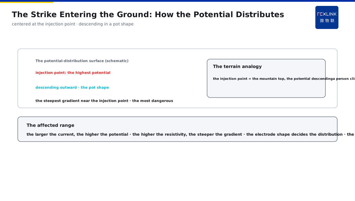
Direct Answer
When the ground resistance is "up to standard", why should we still care whether a person on the grounding grid may get an electric shock? The answer: when the lightning current is injected into the grid, the current spreads from the electrode into the soil, and the ground surface forms a potential-distribution surface centered at the injection point — a person standing nearby and touching the grounded metal with the hand bears the "touch voltage", and the two feet spanning the potential gradient bear the "step voltage"; the equalizing strips, the extension and the burial depth of the grounding grid are precisely to press this potential gradient below the safe value.
At a substation, during a post-strike inspection, an operator standing at the edge of the grounding grid with both hands on the cabinet door felt a strong tingling the moment the lightning current entered the ground; the measurement found that the ground potential gradient at that place far exceeded the safe value and the touch voltage was near the danger threshold. After the equalizing strips were laid along the wall and the grid was densified, no more tingling occurred under the same kind of strike. The key distinction: the "up-to-standard" ground resistance does not equal personal safety — when the lightning current enters the ground, the ground potential shows a surface distribution, and the touch voltage (the hand touching the grounded metal) and the step voltage (the feet spanning the gradient) are what a person actually bears; the equalizing strips/extensions/burial depth press the gradient below the safe value.
Why:
- The potential distribution: the ground potential shows a surface centered at the injection point;
- The touch voltage: the potential difference between the hand touching the grounded metal and the feet standing;
- The step voltage: the voltage difference of the two feet spanning the potential gradient;
- The equalizing means: the equalizing strips, the extension and the burial depth flatten the gradient.
Key insight: "The up-to-standard ground resistance does not equal personal safety — when the lightning current enters the ground, the ground potential shows a surface distribution, and the touch and step voltages are what a person actually bears; the equalizing strips flatten the potential, the extension spreads the gradient, and the burial depth presses the gradient — the three tools press the voltage below the safe value."
At a construction site, the tower-crane grounding resistance passed the test, but after a strike, high-voltage tingling appeared on the nearby ground; the investigation found that the electrode was only a single vertical grounding body, with the potential gradient concentrated and no equalizing measure. After the ring equalizing strip was added, the ground potential gradient became obviously gentle. Lesson: the qualified resistance only shows the discharge capability, and the potential gradient decides personal safety — a single electrode concentrates the gradient, and the equalizing strip spreads it to be safe.
Overview: run "how the potential distributes after the lightning current enters → where the touch/step voltages come from → how the equalizing grid flattens the gradient → why the two voltages must still be checked when the resistance is qualified" as one safety cognition. The qualified ground resistance does not mean that a person near the grid is safe. When the lightning current is injected into the grid, the current spreads from the electrode into the soil, and the ground surface forms a potential-distribution surface centered at the injection point: a person standing nearby and touching the grounded metal bears the touch voltage, and the two feet spanning the potential gradient bear the step voltage. The equalizing strips, the extension and the burial depth of the grounding grid are precisely to press this potential gradient below the safe value. The four layers are unfolded below.
A "terrain" analogy: think of the ground potential distribution as a terrain. The injection point is the "mountain top" with the highest potential; the current spreading outward is like the mountain body descending gently to all sides; the touch and step voltages are like a person "climbing" this terrain — when the hand touches the metal, the hand and the feet stand at different heights (the touch voltage), and when the two feet are apart, they stand at different heights (the step voltage). The equalizing strip is like building "terraces" on the slope, cutting the steep slope into gentle steps, and the drop a person crosses becomes small. The terrain analogy: the injection point = the mountain top with the potential descending outward; the touch/step voltage = the drop of a person climbing this slope; the equalizing strip = the terraces on the slope, cutting the steep slope into gentle steps with a smaller drop.
1. The Strike Entering the Ground: How the Ground Potential Distributes
Step one: first look at what shape the ground potential takes when the lightning current enters.
The potential-distribution surface:
- The current spreads from the electrode into the soil;
- The potential is highest centered at the injection point;
- Gradually decreasing outward;
- Forming a "pot-shaped" surface.
The affected range:
- The larger the current, the higher the potential;
- The higher the soil resistivity, the steeper the gradient;
- The electrode shape decides the distribution;
- The longer the extension, the gentler the gradient.
The danger zone:
- The gradient is steepest near the injection point;
- The potential changes greatly at the electrode edge;
- The areas where people move must be checked;
- The potential gradient is the danger source.
Key insight: "The strike entering the ground forms a potential surface — the current spreads from the electrode, the potential is highest at the injection point and descends outward in a pot shape; the larger the current/the higher the soil resistivity, the steeper the gradient, and the gradient is steepest and most dangerous near the injection point."
2. The Two Voltages: Where They Come From and How the Body Path Goes
Step two: the definitions of the touch and step voltages and the body paths.
The touch voltage:
- The hand touching the grounded metal equipment;
- The feet standing on the ground;
- The potential difference between the hand and the feet;
- The current entering the ground through the hand-body-feet.
The step voltage:
- The two feet standing apart;
- The two feet spanning the potential gradient;
- The potential difference between the two feet;
- The current entering through one foot-body-the other foot.
The danger degree:
- The higher the voltage, the more dangerous;
- The current path decides the consequence;
- The touch voltage near the heart is risky;
- The step voltage is mainly through the legs.
Key insight: "The two voltages depend on the path — the touch voltage is the potential difference between the hand touching the grounded metal and the feet standing (the current through the hand-body-feet, risky near the heart); the step voltage is the difference of the two feet spanning the gradient (mainly through the legs) — both become dangerous as the potential gradient increases."
3. The Equalizing: How to Flatten the Potential Gradient
Step three: the equalizing strips, the extension and the burial depth are the three tools to press the gradient.
The equalizing strips:
- The equalizing strips laid in the grounding grid;
- The grid making the potential distribution even;
- The small potential difference between the adjacent grids;
- The gradient greatly reduced.
The extension and the burial depth:
- The electrode extension spreading the gradient;
- The burial depth avoiding the high surface gradient;
- The deep burial making the current spread faster;
- The ground potential more gentle.
The combined effect:
- The equalizing grid flattening the potential;
- The extension spreading the gradient;
- The depth reducing the surface potential;
- The three tools pressing the voltage below the safe value.
Key insight: "The three equalizing tools — the equalizing grid makes the potential distribution even (the small difference between the adjacent grids), the electrode extension spreads the gradient, and the deep burial makes the current spread faster — the three tools press the ground potential gradient below the safe value."
A rough on-site way to "check the two voltages": when patrolling, the voltage cannot be precisely measured; roughly judge the risk by three points. One, "the distance between the person and the grid" — the closer to the injection point (near the electrode/down conductor), the steeper the gradient, and keep away during the strike; two, "whether the equalizing measure exists" — with the equalizing grid in the grid and the equalizing strip along the wall, the gradient is spread and the risk is low; three, "whether the work is done in the thunderstorm weather" — working on the grid and touching the metal equipment during the thunderstorm is the high-risk action of the touch/step voltage and should be stopped. With the three points roughly judged, keeping away from the injection point and not touching the metal during the thunderstorm is the most direct avoidance. The three-point check: the distance to the injection point (the closer, the steeper), whether the equalizing measure exists (the grid/strip spreading the gradient), and whether the thunderstorm-weather work (touching the metal is high-risk) — keeping away from the injection point and not touching the metal during the thunderstorm is the most direct avoidance.
4. Why the Two Voltages Must Still Be Checked When the Resistance Is Qualified
Step four: the qualified ground resistance and the personal safety are two dimensions.
What the qualified resistance shows:
- The discharge capability up to the standard;
- The total potential rise under control;
- Not equal to the even gradient distribution;
- The local gradient may still be steep.
The two-voltage check:
- The touch voltage per the standard limit;
- The step voltage per the standard limit;
- Checked by the measurement/calculation;
- The equalizing measure needed when not up to the standard.
Why often neglected:
- Only the resistance measured, not the gradient;
- The potential distribution hard to see intuitively;
- The strike occasional and hard to notice;
- The hidden danger lying until the strike day.
Key insight: "The qualified resistance does not equal the safe gradient — the resistance only shows the discharge capability and the total potential under control, and the local gradient may still be steep; the touch/step voltages are checked per the standard limits, the equalizing is added when not up to the standard, and the gradient hidden danger is invisible at ordinary times and exposed on the strike day."
An on-site understanding of "the resistance and the gradient are two dimensions": a ground-resistance test has only "one number", but the grid safety depends on "one picture" — the potential-distribution surface. The resistance measures the total discharge capability, and the gradient sees the local potential drop; the qualified resistance shows that the lightning current can be discharged, and whether the gradient is steep decides where a person stands safely. So the standard acceptance does not end after the resistance test; the two voltages are checked per the limits, and the equalizing is added when not up to the standard. The two dimensions: the resistance = the total discharge capability (one number), and the gradient = the local potential drop (one picture) — after the resistance test, the two voltages are still checked, and the equalizing is added when not up to the standard.
The momentary danger window of personal safety during the strike: the danger of the touch/step voltages exists only at the moment the lightning current enters the ground — after the current disperses, the potential recovers, so it is hidden: everything is normal during the ordinary patrol, and the high voltage appears only in the few milliseconds of the strike. This brings two consequences: one, the danger is bound with the strike event, and the patrol/work risk soars during the thunderstorm weather; two, the ordinary test cannot measure the momentary gradient, and only the design check and the equalizing measure can cover it. The momentary danger window: the touch/step voltages appear only at the moment the lightning current enters the ground (not measurable at ordinary times) — the thunderstorm-weather patrol risk soars, and the design check and the equalizing cover it.
5. Product Implementation: The Ground State Made Monitorable
WeiWuLian products bring the grounding and potential safety to the verifiable level:
- FR ground-resistance monitor: the ground resistance monitored online;
- The trend warning: the grounding degradation found in advance;
- The data review: the grid state compared after the strike;
- The loop improvement: the equalizing effect verified.
The design principle in one sentence: "The resistance monitored and the gradient checked — the FR monitors the ground resistance and the degradation trend online, the touch/step voltages are rechecked after the strike, and the equalizing effect is closed in the data loop."
6. Common Understanding Misjudgments
- "The qualified ground resistance is safe": wrong. The potential gradient decides personal safety; the qualified resistance does not equal the even gradient.
- "Only touching the ground wire gives a shock": wrong. The step voltage may give a shock without touching the metal.
- "The equalizing strip is optional": wrong. A single electrode concentrates the gradient; the equalizing strip spreads it.
- "Far from the injection point is safe": wrong. The injection point of the lightning current is uncertain, and every place of the grid must be checked.
- "The burial depth does not matter": wrong. The deep burial makes the current spread faster and the surface gradient more gentle.
Scope and Limitations
This article explains the ground-grid potential distribution during a strike and the touch/step voltages (the potential surface, the two-voltage paths, the three equalizing tools, and the two dimensions of the resistance and the gradient), applicable to the grounding-safety design and acceptance judgment. The specific voltage limits and the check methods follow GB/T 50065-2011; this article explains only the physical mechanism. All cases are anonymized (a substation/a construction site) and do not refer to any specific customer.