 微物联研究院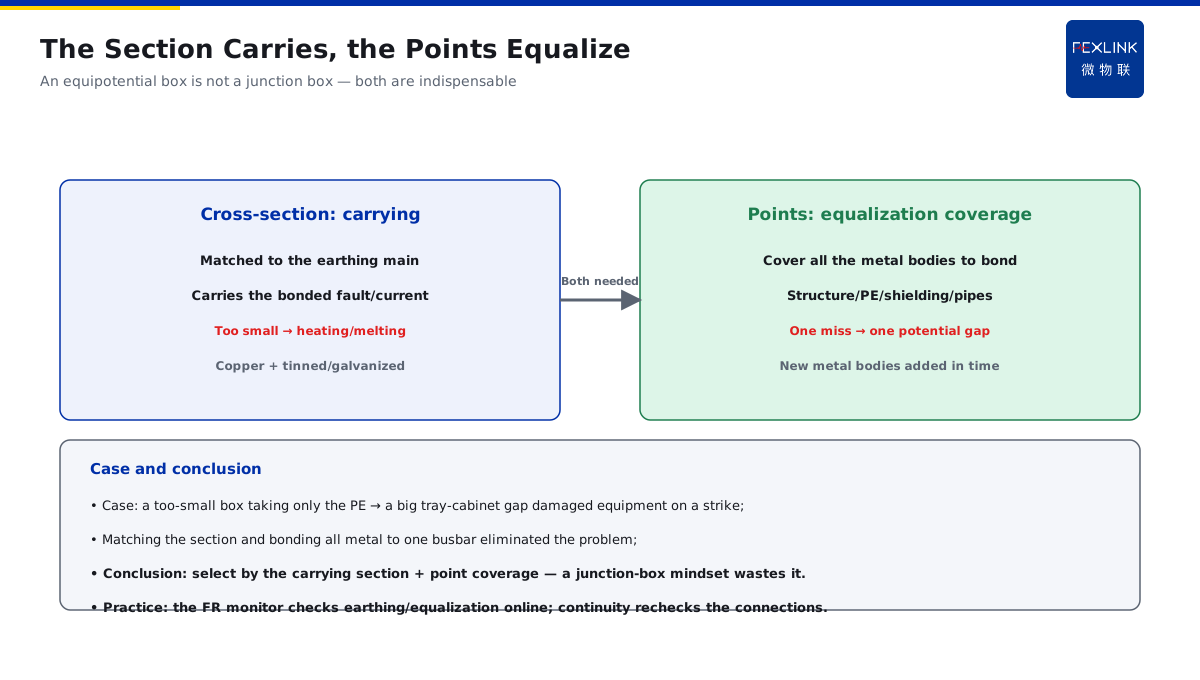
Direct Answer
What cross-section should the equipotential terminal box in a server room or switch room have, and which wires must it take? The answer: the cross-section of the equipotential busbar must be able to carry the bonded fault/lightning current (matched to the cross-section of the connected earthing main), and it must bond the building metal structure, the PE main, the shielding layers and the entering/exiting pipes on the same busbar. The key of selection is not the appearance, but whether the current-carrying capacity of the cross-section and the number of connection points cover all the metal bodies in this area that need bonding.
At a server room, the equipotential terminal box had a too-small cross-section and only took the PE main, not the tray and the shielding: during a strike, the potential difference between the tray and the cabinets was large, and equipment was damaged. After matching the cross-section to the connected earthing main and bonding the tray/shielding/pipes to the same busbar, the problem disappeared. The key distinction: an equipotential box is not an "ordinary junction box" — the cross-section handles the current-carrying capacity (matched to the earthing main), and the connection points handle potential equalization (covering all the metal bodies in this area); both are indispensable.
Why:
- Cross-section: carries the bonded fault/lightning current, matched to the earthing main;
- Connection points: cover the metal bodies to bond (structure/PE/shielding/pipes);
- Contact: the connections are reliable and low-impedance;
- Location: the main and local equipotential points are set as needed.
Key insight: "Selection looks at two things: is the cross-section enough to carry, and are the connection points complete — treating it as an ordinary junction box means it is installed for nothing."
At a switch room, a newly added cable tray was not connected to the equipotential busbar; during a strike, the tray potential was unequal to the equipment, arcing damaged it, and connecting the tray to the busbar fixed it. Lesson: newly added metal bodies (trays/pipes/equipment enclosures) must be brought into the equipotential system in time — every missing connection point leaves a potential-difference risk.
1. Matching the Busbar Cross-Section to the Earthing Main
Step one: how the cross-section is set.
The role of the cross-section:
- Carries the bonded fault/lightning current;
- The current equalizes and shunts through the busbar;
- A too-small section → heating/melting;
- It is the first indicator of selection.
The matching basis:
- Matched to the cross-section of the connected earthing main;
- Of the same order as the PE main/down-conductor;
- Reference the standard minimum-section requirements;
- Stricter for large-current scenarios.
Material and corrosion protection:
- Mainly copper (good conductivity);
- Tinned/galvanized for corrosion;
- Stronger protection in humid environments;
- The material affects contact and life.
Key insight: "The cross-section is matched to the earthing main to carry the bonded current — too small means heating and melting; look at the carrying capacity first, not the appearance."
2. The Types of Metal Bodies That Must Be Bonded
Step two: what the busbar must take.
Building metal structures:
- Steel frames/column bars;
- Slab reinforcement/exterior metal;
- The structure is a natural equalization net;
- It must connect to the busbar.
The PE main:
- The protective earthing main;
- The PE of each circuit;
- Bonded at one point on the busbar;
- Avoid multi-point earthing loops.
Shielding layers:
- Cable shielding/trays;
- The lightning shielding system (connecting to LPZ);
- Shielding metal must be equipotential;
- Prevents induced overvoltage.
Entering/exiting pipes:
- Water/gas pipes/trays;
- Metal pipes entering the area;
- Bonded at the entrance;
- Prevents "potential coming in through the pipes".
Key insight: "The structure, PE, shielding and entering/exiting pipes — four types — must meet on the same busbar; missing one leaves a potential-difference channel."
3. The Contact Reliability of the Connections
Step three: is it connected firmly.
Connection methods:
- Bolted (removable, easy to maintain);
- Welded (permanent, low resistance);
- Crimped terminals/lugs;
- Choose the method by the part.
Contact requirements:
- Clean, unoxidized contact surfaces;
- Enough tightening torque;
- Low contact resistance;
- Regular continuity checks.
Common problems:
- Oxidized contacts → rising resistance;
- Loose bolts → virtual connection;
- Unremoved paint/oxide layers;
- Unreliable connections → failed equalization.
Key insight: "The connections must be reliably contacted and low-impedance — oxidation/looseness/virtual connections make the equalization nominal; test the continuity regularly."
4. Where to Set the Main and Local Equipotential Points
Step four: where to install and how many.
Main equipotential bonding (MEB):
- Set at the building entry;
- Summarizes all the building metal;
- At the incoming switchgear;
- The whole building's potential reference.
Local equipotential bonding (LEB):
- Server rooms/switch rooms/bathrooms, etc.;
- Locally bonds the metal in the area;
- Key for sensitive areas;
- Connected to the main.
Setting points:
- Set at the area entrance;
- Reliably connected to the earthing system;
- Independent local busbars in local areas;
- Clear main-local hierarchy.
Key insight: "The main handles the whole-building reference, the local handles sensitive areas — set them by area; do not mix the hierarchy."
5. The Selection Check: Cross-Section, Connection Points, Material and Corrosion
Step five: how to check in practice.
The checklist:
- ① The cross-section matches the earthing main, with enough carrying capacity;
- ② The connection points cover all the metal bodies in this area;
- ③ Good conductivity and adequate corrosion protection;
- ④ Reliable connections, testable continuity;
- ⑤ A clear main/local hierarchy.
Common pitfalls:
- Selecting by the "junction box" mindset;
- Too small a section and incomplete points;
- Missing newly added metal bodies;
- Unprocessed contact surfaces and virtual connections.
Practice verification:
- Verify the connections by continuity testing;
- Monitor online with the FR Earth-Resistance Monitor;
- Recheck the equalization after strikes;
- Bring new metal bodies into the system in time.
Key insight: "Select with a checklist: enough section, complete points, good material, firm connections, clear hierarchy — only when all five pass is the selection right."
6. Product Implementation: Equalization and Earthing as One
WeiWuLian products manage the equipotential system:
- FR Earth-Resistance Monitor: online earthing and equalization state;
- Continuity recheck: continuity tests of the connection points;
- Strike-event correlation: rechecking the equalization after strikes;
- Data loop: digitizing the section/points/state.
The design principle in one sentence: "Section by the main, complete connection points, reliable contact, clear hierarchy — manage the equipotential system with data."
7. Common Misjudgments
- "Treat it as an ordinary junction box": ignoring the equalization role. Result: small section, incomplete points. Correct: match the main and cover the metal bodies.
- "Any section works": ignoring the carrying capacity. Result: heating and melting. Correct: match the main's section.
- "Missing the tray is fine": ignoring the potential difference. Result: arcing on a strike. Correct: bring new metal bodies in.
- "Connected and done": ignoring contact reliability. Result: virtual connection, failed equalization. Correct: test the continuity.
- "Mix the main and local": ignoring the hierarchy. Result: unclear reference. Correct: a clear main/local structure.
Scope and Limitations
This article explains the section matching, connection-point coverage, contact reliability, main/local equipotential settings and a selection checklist for equipotential terminal boxes and earthing busbars, applicable to selecting and understanding equipotential systems. The exact sections and layouts follow GB 50057-2010, GB 50343-2012 and their revisions; this article explains only the selection logic and judgment basis. All cases are anonymized (a server room, a switch room) and do not refer to any specific customer.