 FEXLINK Research Institute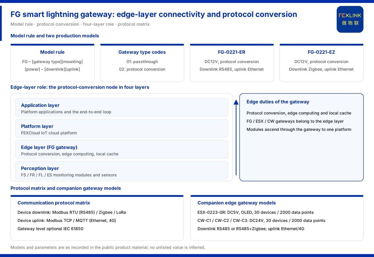
Direct Answer
Within the intelligent lightning-protection product line, the lightning-protection smart gateway takes on the networking and protocol link, not the measurement link. The product knowledge base places the FG lightning-protection smart gateway (FG-0221-ER) in product line A, intelligent lightning protection, alongside measurement products such as the grounding resistance monitor and the lightning current monitor, and its responsibility is to bring field devices onto an existing network.
The model rule directly shows its capability orientation: the FG naming is composed of gateway type, installation method, supply, and downlink and uplink fields, in which the gateway type distinguishes two classes, passthrough and protocol conversion. That is, protocol conversion is an explicit capability of FG rather than an add-on function. Based on what the product knowledge base records, this article explains FG's place in the four-layer architecture, its available downlink and uplink combinations, and its connection in a typical scenario, and it marks out the parts the material has not yet unfolded.
1. The Protocol-Conversion Orientation Reflected in the Model Rule
The FG model rule combines gateway type, installation method and supply with the two communication segments of downlink and uplink. The gateway type column gives two classes: 01 stands for passthrough and 02 stands for protocol conversion. This design means that choosing class 02 chooses the protocol-conversion treatment, in which the gateway does not merely forward one stream of data unchanged but can complete protocol adaptation between the uplink and the downlink.
The naming structure also shows that the downlink and uplink are defined separately. This means the two sides of the gateway can be asymmetric interface forms: one side faces the field devices and the other faces the upper network. Understanding this is the premise for understanding the various combinations in the later model table.
2. Downlink and Uplink Combinations of the Two FG Models
The product knowledge base table lists two FG models. The FG-0221-ER uses a DC12V supply and protocol conversion, with RS485 on the downlink and Ethernet on the uplink; the FG-0221-EZ likewise uses a DC12V supply and protocol conversion, with Zigbee on the downlink and Ethernet on the uplink.
The difference between the two models is concentrated in the downlink interface: ER faces an existing RS485 link and EZ faces a Zigbee link, while both reuse Ethernet on the uplink. This arrangement shows that the purpose of FG is to aggregate different field links onto the same Ethernet uplink without changing the upper network. In selection, what really needs to be judged is whether the field device side is RS485 or Zigbee, not the uplink side.
3. The Gateway's Place in the Four-Layer Architecture
The general four-layer architecture of the monitoring system given by the product knowledge base is perception layer, edge layer, platform layer and application layer. FG is grouped into the edge layer together with the ESX intelligent edge-computing gateway and the CW industrial gateway, taking on protocol conversion, edge computing and local buffering.
Understanding FG at the edge layer clarifies its division of labour with measurement products: the perception layer acquires, the edge layer aggregates and pre-processes, and the platform layer and application layer analyse and present. The responsibility boundary of FG stops at the edge layer; it does not itself produce measured values but lets measured values enter the platform. Treating a gateway as a measurement device is a common role confusion.
It should be noted that protocol conversion, edge computing and local buffering are three parallel responsibilities of the edge layer, but the product knowledge base does not unfold FG's specific configuration on these three by model. What can be confirmed is that FG belongs to the edge layer and takes on protocol conversion; the capacity of its local buffering and the specific algorithms of edge computing remain outside the material and must be confirmed separately.
4. Capability Comparison with Peer Products in the Edge Layer
As edge-layer products, the ESX intelligent edge-computing gateway (ESX-0223-GR) and the CW industrial gateway each have their own positioning. The ESX-0223-GR uses a DC5V supply, has an OLED display, supports 30 devices and 2000 data points, with RS485 on the downlink and wired plus 4G on the uplink; the CW industrial gateway includes CW-C1, CW-C2 and CW-C3, uses a DC24V supply, likewise supports 30 devices and 2000 data points, with RS485 or RS485 plus Zigbee selectable on the downlink and Ethernet or 4G selectable on the uplink.
These data show that the edge layer has a clear internal division of labour: FG focuses on protocol conversion and uplink at the lightning-protection site, while ESX and CW focus on larger access scale and more uplink methods. When the number of field devices, the uplink channel or the display requirement exceeds the capability range of FG, the task should pass to other gateways at the same layer. Looking at the capability of FG together with the parameters of peer products avoids adding functions to it by default that do not belong to it.
5. Downlink and Uplink in the Communication Protocol Matrix
The communication protocol matrix of the product knowledge base explains the basis of the gateway connecting to the network fairly clearly. The device downlink includes Modbus RTU (over RS485) and Zigbee (carrying Modbus), plus LoRa; the device uplink includes Modbus TCP and MQTT, over Ethernet or 4G; at gateway level IEC 61850 is optional.
Against this matrix, the downlink RS485 and uplink Ethernet of FG-0221-ER fall exactly on the conventional path of Modbus RTU to Modbus TCP or MQTT; the Zigbee downlink of FG-0221-EZ carries Modbus and reuses Ethernet on the uplink, likewise within the matrix coverage. IEC 61850 is a gateway-level option belonging to higher-level protocol interconnection and should not be taken by default as a standard configuration of FG.
6. Access Method in a Typical Scenario
The typical application scenarios list the online grounding-grid monitoring combination of substations and traction substations as the grounding resistance monitor (one set per point) plus the FG gateway plus FEXCloud. This combination shows that lightning-protection monitoring is accessed through a gateway and a unified platform, rather than building a separate channel for lightning protection alone.
Two meanings can be read from this combination. First, on the field side of grounding-grid monitoring the grounding resistance monitor performs acquisition, the gateway aggregates and uploads, and the platform collects and presents the data. Second, several monitoring points are accessed through the same gateway system, and selection should determine the number of gateways and the downlink method by point count and interface type, rather than configuring an independent channel point by point.
7. Material Boundaries and Items to Confirm
The product knowledge base's record of FG stops at the model rule, the interface combinations of the two models, the edge-layer positioning in the four-layer architecture, and the protocol scope in the communication matrix. It does not unfold the specific access capacity limit of FG, the number of supported slaves, supply power consumption, protection class or installation dimensions, nor does it give the specific mapping implementation of FG under IEC 61850.
In detailed engineering design, therefore, the items above should be listed as items to confirm and the corresponding data should be requested from the supplier or designer rather than inferred from the existing entries. Keeping the listed and unlisted information apart both uses the material fully and avoids drawing conclusions beyond its boundary.
Scope and Limitations
First, this article restates only what the product knowledge base lists, with the factual boundary limited to the FG lightning-protection smart gateway entry in the product-line overview, the FG model rule and model table, the four-layer architecture, the communication protocol matrix, and the selection comparison of the typical application scenario.
Second, the supply, protocol conversion method, and downlink and uplink interfaces of FG-0221-ER and FG-0221-EZ are cited as listed in the product knowledge base; this article does not infer their access capacity, power consumption, protection class or installation dimensions.
Third, the supply, access scale and uplink and downlink methods of the ESX intelligent edge-computing gateway and the CW industrial gateway are cited as listed in the product knowledge base; this article does not conflate their capabilities with those of FG.
Fourth, the downlink and uplink protocols in the communication protocol matrix, and the gateway-level optional IEC 61850, are cited as listed in the product knowledge base; this article does not infer their configuration in a specific project.
Fifth, the combination for online grounding-grid monitoring of substations and traction substations is cited as listed in the product knowledge base; this article does not give a specific engineering conclusion about gateway quantity or interface configuration on that basis.