 FEXLINK Research Institute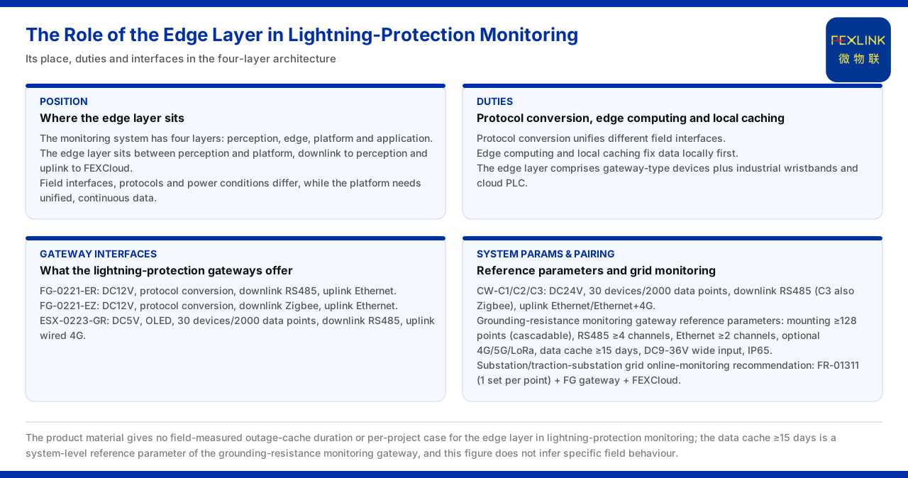
The Role of the Edge Layer in Lightning-Protection Monitoring
Lightning-protection monitoring sites are often dispersed: grounding-resistance monitoring points lie across the grounding grid, surge protective device monitoring points inside distribution cabinets, and lightning-current monitoring points on the incoming side. The interfaces, protocols and supply conditions of these points are not uniform, while the platform needs unified, continuous data. The edge layer exists to resolve this contradiction. The product knowledge base divides the monitoring system into four layers; the edge layer sits between the perception layer and the platform layer, is composed of gateway-type devices together with industrial wearables and cloud PLCs, and carries the three duties of protocol conversion, edge computing and local caching.
This article follows the knowledge base records to explain the edge layer's position in lightning-protection monitoring, what problem each of the three duties solves, what interfaces the lightning-protection smart gateway provides, and how it connects with the platform layer FEXCloud. It should first be noted that the material gives conventions at the architecture and interface level, not field-measured conclusions of any specific project.
1. The Position of the Edge Layer in the Four-Layer Architecture
The knowledge base divides the monitoring system into four layers. The perception layer handles acquisition, the edge layer conversion and caching, the platform layer is the FEXCloud IoT cloud platform, and the application layer carries business use. The edge layer connects downward to the perception layer and upward to the platform layer.
This position determines the edge layer's dual role. Downward, it must be able to connect device-facing interfaces such as RS485 and Zigbee; upward, it must provide platform-receivable data over Ethernet or 4G. It is neither a pure acquisition device nor an analysis platform but the conversion and convergence gateway between the two. In lightning-protection monitoring, it is precisely because the field-device interfaces differ that this gateway becomes necessary.
2. Protocol Conversion: Unifying Different Field Interfaces
The knowledge base lists protocol conversion as the edge layer's first duty. The device downlink supports Modbus RTU (RS485), Zigbee (Modbus) and LoRa; the device uplink supports Modbus TCP or MQTT, carried over Ethernet and 4G, and at the gateway level optionally IEC 61850.
The uplink and downlink protocols differ, which is exactly why conversion is needed. Field devices communicate with protocols such as Modbus RTU facing a serial link, while the platform side uses IP-based Modbus TCP or message-oriented MQTT. The edge layer turns the former into the latter, letting data cross the network boundary between the field and the cloud. IEC 61850, as an optional gateway-level uplink, shows that in specific power scenarios the edge layer can also provide another standardised interface upward. For lightning-protection monitoring, protocol conversion means monitoring points with different interfaces can enter one data system.
3. Edge Computing and Local Caching
The knowledge base lists edge computing and local caching side by side as the edge layer's other two duties. Edge computing lets part of the processing be completed on site; local caching keeps data from being lost when the link is temporarily interrupted.
These two duties bear directly on lightning-protection monitoring. Lightning-protection sites are mostly outdoors or unattended, and network conditions are not always stable. If all data had to be uploaded in real time, a link interruption would create a data gap; local caching lets data fall to the edge layer first and be back-filled once the link recovers. Edge computing reduces the volume that must be uploaded and spares processing with high real-time requirements from a round trip to the cloud. In this sense, the edge layer protects the completeness and continuity of data, and these two points are the foundation for the long-term usability of lightning-protection monitoring.
4. What Interfaces the Lightning-Protection Smart Gateway Provides
The knowledge base records two lightning-protection smart gateways: the lightning-protection smart gateway FG-0221-ER has a DC12V supply, supports protocol conversion, with RS485 downlink and Ethernet uplink; FG-0221-EZ has a DC12V supply, supports protocol conversion, with Zigbee downlink and Ethernet uplink.
The division between the two appears in the downlink interface. ER's downlink is RS485, suitable for monitoring points connected over a serial bus; EZ's downlink is Zigbee, suitable for wirelessly networked points. Both have Ethernet uplink, showing they face sites where Ethernet is reachable. For a lightning-protection monitoring designer, which to choose depends on whether the field monitoring points are wired or wirelessly networked, while both follow the same path on the uplink side into the platform.
5. Access Capability of Other Edge-Layer Devices
Besides the lightning-protection smart gateway, the knowledge base also lists the intelligent edge-computing gateway and industrial gateways. The intelligent edge-computing gateway ESX-0223-GR has a DC5V supply with an OLED display, an access capacity of 30 devices and 2000 data points, RS485 downlink and wired 4G uplink.
The industrial gateways CW-C1, CW-C2 and CW-C3 have a DC24V supply and the same access capacity of 30 devices and 2000 data points; on the downlink, C1 and C2 use RS485 and C3 also includes Zigbee; on the uplink, they use Ethernet and Ethernet plus 4G respectively. Placing these capabilities in the context of lightning-protection monitoring, 30 devices and 2000 data points are the scale one edge-layer device can take on, and the DC supply corresponds to the power conditions available on site. The difference in uplink method determines whether the link from the edge layer to the platform is wired or wireless.
6. System-Level Reference Parameters and the Grounding-Grid Online Monitoring Combination
The knowledge base also gives the reference parameters of the intelligent gateway of the grounding-resistance monitoring system: more than 128 mount points with cascade support, no fewer than 4 RS485 ports, no fewer than 2 Ethernet ports, selectable 4G, 5G or LoRa, a data cache of more than 15 days, a DC9 to 36V wide-voltage supply and an IP65 protection rating.
These parameters describe a system-level reference convention. The mount points and cascade support show the edge layer can scale with site size; the multiple RS485 and Ethernet ports show it must connect several directions at once; and the wide-voltage supply and IP65 show it faces field power and outdoor environments. The typical application scenarios of the knowledge base further give: the recommended combination for online monitoring of the grounding grid of a substation or traction substation is the grounding resistance monitor FR-01311 (1 set per point), the lightning-protection smart gateway and FEXCloud. This combination links the perception, edge and platform layers, with the edge layer handling data convergence and upload.
Applicability and Limits
- This article restates only what the knowledge base lists; its factual boundary is the four-layer architecture and edge-layer duties of the monitoring system, the communication-protocol matrix, the models and interfaces of the lightning-protection smart gateway, the intelligent edge-computing gateway and the industrial gateways, the reference parameters of the intelligent gateway of the grounding-resistance monitoring system, and the recommended combination for grounding-grid online monitoring.
- The supply, downlink and uplink interfaces of FG-0221-ER and FG-0221-EZ are cited as listed; this article does not infer their port count, installation method or protection rating.
- The access capability and up/down methods of the intelligent edge-computing gateway ESX-0223-GR and the industrial gateways CW-C1, CW-C2 and CW-C3 are cited as listed; this article does not infer their networking topology in a specific project.
- Parameters such as the data cache of 15 days are system-level reference parameters of the intelligent gateway of the grounding-resistance monitoring system, cited as listed; the knowledge base gives no field-measured data or per-project case of outage cache duration in lightning-protection monitoring, and this article does not infer specific field performance or add cases.
- IEC 61850 is an optional gateway-level uplink, cited as listed; this article does not infer its concrete configuration in lightning-protection monitoring.