 FEXLINK Research Institute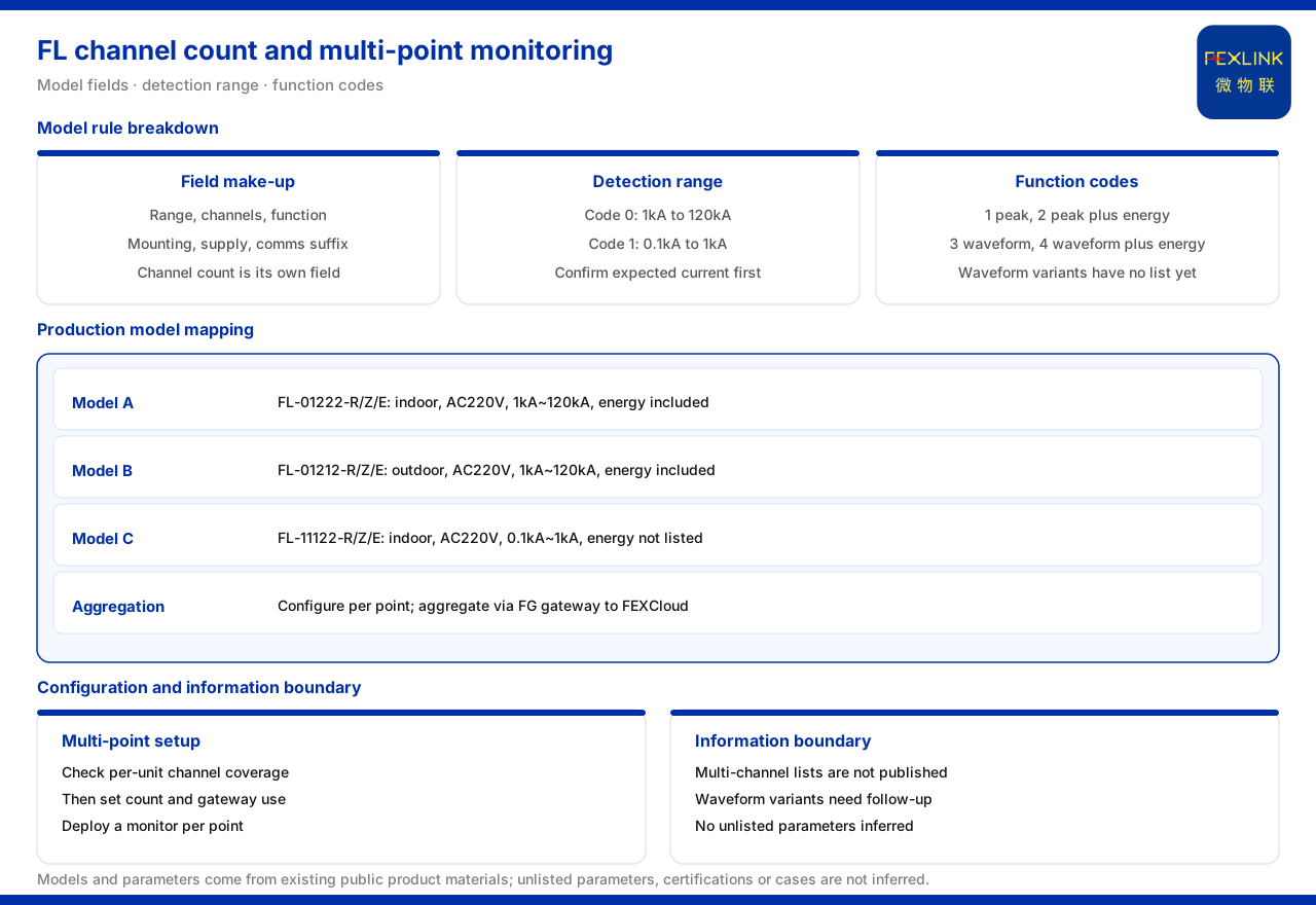
How to Configure FL Channel Count and Multi-Point Monitoring
Direct answer: configuring multi-point lightning current monitoring has two steps: first see whether one FL unit can cover the channel requirement of that point, then decide how many units are needed and whether a gateway should aggregate them. The model rule of the FL lightning current / transient current monitor in the material contains an independent "channel count" field, which shows that the same series can be distinguished by channel count; when there are many points, the sound practice is to configure a monitoring device per point and aggregate through the FG lightning-protection smart gateway before uploading to the platform. The material does not give a production selection table for the multi-channel class, which must be noted during configuration.
What Fields the FL Model Rule Contains
The FL model rule in the material can be broken into several fields: detection range, channel count, function, installation method and supply, followed by a communication suffix at the end. "Channel count" is an independent field, which in itself shows that the FL series supports distinction by channel count, not only by detection object. In other words, when a site needs to monitor multiple current channels, the channel-count field is the starting point of configuration.
The detection-range code also has a clear meaning: code 0 corresponds to 1kA to 120kA, and code 1 corresponds to 0.1kA to 1kA. This means one FL series can cover two classes of lightning current, from smaller to larger, and configuration should first confirm the expected current level of the monitored object and then choose the corresponding range.
The function code also needs attention: function 1 is peak, function 2 is peak plus energy, function 3 is waveform and function 4 is waveform plus energy. The higher the function, the richer the information that can be recorded; but the material also states that the waveform classes (functions 3 and 4) have no production selection table at present, so if a scheme requires waveform recording, the available models should be confirmed from later data.
Channel Count and Function in Production Models
The production models listed in the material are three lightning current monitors: the indoor FL-01222-R/Z/E, the outdoor FL-01212-R/Z/E and the range-code-1 FL-11122-R/Z/E. The first two belong to detection-range code 0, covering 1kA to 120kA, both supporting energy and both supplied at AC220V. The third belongs to detection-range code 1, covering 0.1kA to 1kA, with indoor installation and AC220V supply, and the material notes that it does not list energy.
All three models offer communication options as -R, -Z and -E, corresponding to RS485, Zigbee and Ethernet respectively. It can be seen that the production models already form several combinations of detection range, installation method and function, but within the scope of the material no production selection table for the multi-channel class is listed, nor is a concrete way given for one model to cover several points. This directly affects how multi-point monitoring is configured.
Why Multi-Point Monitoring Needs a Gateway
Multiple points mean more than one data source. If each device uploads separately, management on the platform side becomes scattered and the site needs more independent communication links. The FG lightning-protection smart gateway in the material comes in two protocol-conversion versions, the FG-0221-ER with RS485 downlink and the FG-0221-EZ with Zigbee downlink; both have an Ethernet uplink and both can be used for network aggregation of multi-point monitoring data. Connecting the monitoring devices of several points to the gateway over RS485 or Zigbee and letting the gateway upload uniformly is a comparatively clear networking method.
In the larger system, the gateway belongs to the edge layer. In the four-layer architecture given by the material, the edge layer is handled by the FG, ESX and CW gateways plus the CX industrial wearable and the CC cloud PLC for protocol conversion, edge computing and local buffering, and the platform layer is the FEXCloud IoT cloud platform. That is, multi-point FL data can first be aggregated and buffered at the edge layer and then enter the platform layer, reducing dependence on a direct network connection at each point.
Configuring Quantity by Point
Given that the material gives no multi-channel production table, the sounder configuration approach is to take the "point" as the basic unit, with one monitoring device per point; if a point genuinely needs multi-channel acquisition, judge from the channel-count field of the model rule whether a corresponding model exists, and then decide whether to use a multi-channel device or to increase the number of devices. This keeps the data source of each point clear and makes later point-by-point troubleshooting easier.
Once the number of points is fixed, plan how the gateway is accessed. If the points are concentrated, several devices can hang on the same RS485 bus and be aggregated by a gateway with RS485 downlink; if the points are scattered, a gateway with Zigbee downlink can be considered to reduce cabling. Finally, check the access capability of the gateway and the site power conditions, to ensure the aggregation layer does not become a bottleneck.
Reading Detection Range and Function Class Together
Detection range determines how large a current the device can acquire, and function class determines what information it can record. The two must be considered together: if the monitored object is mainly a larger lightning current, choose detection-range code 0; for a smaller current, choose code 1. On function, if only whether it occurred and the peak magnitude are needed, the peak class can be chosen; if energy is also needed, the peak-plus-energy class can be chosen. The waveform class carries the richest information, but the material states that it has no production selection table at present, so a model must not be assumed to exist merely from the function class.
For a multi-point project, different points may be at different magnitudes, so it is all the more necessary to fix the detection range and function class per point rather than applying one class to the whole system. Once the range and function of each point are clear, the required number of devices can be totalled, and the configuration will not show an obvious deviation.
Access Order After the Points Are Fixed
Once the points and models are fixed, the access order also affects construction. In general, proceed in the order "fix the gateway position first, then lay out the bus route, then install the end devices": the gateway position determines the aggregation point, the bus route determines the coverage of RS485 or Zigbee, and the end devices are installed by point and then connected. If the points are scattered, Zigbee reduces conduit and cabling; if the points are concentrated, RS485 is easier to manage uniformly. The FG gateway in the material offers both a downlink RS485 version and a downlink Zigbee version, so it can be chosen flexibly by area.
Boundaries to Clarify
What the material confirms is that the FL model rule contains fields for detection range, channel count, function, installation method and supply; the meaning of detection-range codes 0 and 1; the meaning of function codes 1 to 4; the range, installation method, supply and function of the three production models; that the waveform classes have no production selection table at present; and the role of the FG gateway in multi-point aggregation. What the material does not give is the specific models and parameters of the multi-channel class, the specific total quantity to configure per point, and the deployment positions of different points. These belong to system design.
Implementation Recommendations
- First confirm the current range to be monitored at each point, and choose detection-range code 0 or 1 accordingly.
- Clarify what information each point must record: peak, peak plus energy, or waveform; if waveform is involved, first confirm whether a model is available.
- Configure monitoring devices by point, and use the channel-count field to judge the model when multiple channels are needed.
- Plan gateway aggregation: use RS485 downlink for concentrated points and Zigbee downlink for scattered points, with the uplink unified to Ethernet.
- Check the buffering of the edge layer and the platform access method, to avoid the aggregation layer becoming a bottleneck.
Summary
The configuration of multi-point lightning current monitoring hinges on separating the two concepts of "channel count" and "point": channel count decides how many channels one device can acquire, and point decides how many locations must be covered. The FL model rule provides the channel-count field and the function classes, and the production models cover two range classes and several installation methods, but the multi-channel class and the waveform class remain limited by the scope of the material. Taking one unit per point as the baseline and combining it with gateway aggregation is a comparatively sound configuration path supported by the material; the specific quantity and position still have to be determined by the on-site structure.