 FEXLINK Research Institute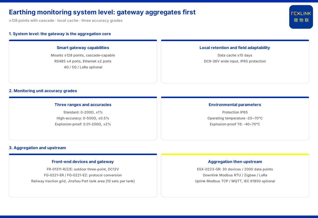
Direct answer
Grounding-resistance monitoring has to cover a large number of scattered points; what makes this possible is not connecting every monitoring unit directly to the platform but first performing one layer of aggregation on site and then sending upward uniformly at the gateway level. The core of the system-level reference parameters in the product knowledge base is the intelligent gateway: a single gateway mounts no fewer than 128 points and can be cascaded, provides no fewer than 4 RS485 channels and no fewer than 2 Ethernet channels, and its wireless part can optionally use 4G, 5G or LoRa. A project with many points can therefore rely on a single gateway to aggregate by multi-point mounting and expand through cascading; when the field bus is insufficient, it can send upward over Ethernet or wirelessly. The system level also requires local retention and site adaptability: a data buffer of no fewer than 15 days, a supply of DC9 to 36 volts wide-voltage, and IP65 protection. On the perception side, the grounding-resistance monitoring units are divided into three accuracy tiers, with ranges of 0 to 200 ohms (standard type), 0 to 500 ohms (high-precision type) and 0.01 to 200 ohms (explosion-proof type). In configuration, first determine the gateway's mounting and cascading by the number and distribution of sites, then choose monitoring units by accuracy requirement, and finally check communication and supply.
1. System-level capability: the gateway is the aggregation core
At system level, the product knowledge base places the emphasis on the intelligent gateway: it mounts no fewer than 128 points with cascading, provides no fewer than 4 RS485 channels and no fewer than 2 Ethernet channels, and offers optional wireless 4G, 5G or LoRa. These indicators show that the basic unit of a system-level design is not an individual monitoring point but a gateway that can mount many points and cascade upward. In selection, first group the site points to the gateway by location and count, then consider cascading and uplink, rather than designing channels point by point.
2. Mounting and cascading: one gateway carrying many points
The first capability of the intelligent gateway is its mounting point count. The system-level parameters require mounting no fewer than 128 points and support cascading. This means a single gateway can carry the aggregation of hundreds of grounding-grid points; when the total exceeds a single unit's capability, or when points span widely separated areas, multiple gateways can be chained by cascading to aggregate upward stage by stage. For a scenario such as grounding-grid monitoring, where points are dense and scattered, this capability directly determines whether a large area can be covered with relatively few aggregation nodes. Estimating the total point count first and then judging whether a single unit or a cascaded set is needed avoids laying out an oversized architecture from the start.
3. Interfaces and uplink: RS485, Ethernet and wireless options
The gateway's downlink and uplink interfaces are likewise given at system level. No fewer than 4 RS485 channels and no fewer than 2 Ethernet channels mean the gateway can connect several groups of field bus at once and has multiple wired uplink channels; the optional wireless 4G, 5G or LoRa provides an uplink choice for points that are inconvenient to cable or are remotely scattered. The front-end monitoring units thus send upward to the gateway over field bus such as RS485, and the gateway then sends data to the platform over Ethernet or wirelessly. The number of field buses and wired uplink channels must match the gateway's interface capability, while the wireless uplink is chosen among 4G, 5G and LoRa by on-site signal coverage and tariff conditions.
4. Local retention and supply protection: buffer, wide voltage and IP65
The system-level parameters also give the gateway's reliability indicators: a data buffer of no fewer than 15 days, a supply of DC9 to 36 volts wide-voltage, and IP65 protection. The data buffer provides local retention before aggregation and uplink; when the uplink is briefly interrupted, the gateway can still hold a period of data and backfill it once the link recovers. Wide-voltage supply accommodates on-site voltage fluctuation and facilitates deployment at grounding-grid points where supply conditions are unstable, while IP65 protection corresponds to outdoor installation environments. If the site has large supply fluctuation or is outdoors, the gateway's wide-voltage range and protection rating should be confirmed sufficient, and the buffer days checked against the backfill requirement after a link break.
5. Monitoring-unit ranges: standard, high-precision and explosion-proof
The perception-side grounding-resistance monitoring units are divided into three tiers by accuracy. The product knowledge base records that the standard type has a range of 0 to 200 ohms with ±1 percent accuracy; the high-precision type has a range of 0 to 500 ohms with ±0.5 percent accuracy; and the explosion-proof type has a range of 0.01 to 200 ohms with ±2 percent accuracy. The three tiers each emphasise something different in range and accuracy: the standard type covers the conventional grounding-grid detection range; the high-precision type offers a larger range and higher accuracy, suited to occasions with stricter measurement-deviation requirements; and the explosion-proof type addresses places such as tank farms that require explosion protection. In selection, fix the tier by the grid's resistance range and the accuracy requirement, then check whether the environment needs explosion protection.
6. Two access forms: the grounding-resistance monitor and the lightning-protection smart gateway
At the product level, the access forms of grounding-resistance monitoring fall into monitor and gateway. The product knowledge base records that the FR grounding-resistance monitor (FR-01311-R/Z/E) is uniformly DC12V, outdoor-mounted and measured by the three-electrode method, with the three types communicating over RS485, Zigbee and Ethernet respectively; it also records that the FR/FRP series has been applied to projects such as online grounding-grid monitoring for railway traction substations and the Jinzhou Port oil-tank area (10 sets per tank). Aggregation is carried by the lightning-protection smart gateway: the product knowledge base records that the FG lightning-protection smart gateway (FG-0221-ER) and the FG lightning-protection smart gateway (FG-0221-EZ) are both DC12V with a gateway type of protocol conversion, the former downlinking RS485 and uplinking Ethernet and the latter downlinking Zigbee and uplinking Ethernet. The monitor's communication suffix must therefore interface with the gateway's downlink method to bring the scattered points into the edge layer.
7. The edge-computing gateway: another uplink node
Beyond the dedicated lightning-protection smart gateway, grounding-monitoring points can also be sent upward through an edge-computing gateway after aggregation. The product knowledge base records that the ESX intelligent edge-computing gateway (ESX-0223-GR) has an access capability of 30 devices and 2000 data points, communicates downward over RS485 and upward over wired and 4G. When the on-site point scale is within the capability of the front-end gateway, the data can be further aggregated to the edge-computing gateway and sent upward uniformly by it. The edge-computing gateway's access capability can be checked against the on-site device and data-point counts to avoid exceeding its carrying range.
8. Protocol matrix and selection check order
The communication protocol matrix of the product knowledge base lists device downlink as Modbus RTU (RS485), Zigbee (Modbus) and LoRa, device uplink as Modbus TCP and MQTT (Ethernet, 4G), and gateway-level IEC 61850 (optional). This lets subordinate devices access over multiple protocols and send upward at the gateway level, so scattered points are aggregated first and uploaded afterwards. Selection can follow this order: first, count the point number and distribution; second, determine the number of gateways by mounting no fewer than 128 points and cascading; third, check RS485 channel count and wireless method against the field bus; fourth, fix the monitoring-unit tier by the resistance under test and the accuracy requirement; fifth, check that the monitor's communication suffix agrees with the gateway's downlink method; and sixth, confirm that buffer, wide-voltage and protection rating meet the site conditions.
Scope and limitations
First, this article restates only what the product knowledge base records; the factual boundary is limited to the grounding-resistance monitoring system (system level) reference parameters, the monitoring-unit ranges, the FR monitor, the FG gateway, the ESX edge-computing gateway and the communication protocol matrix.
Second, the intelligent gateway's mounting point count, RS485 channel count, Ethernet channel count, optional wireless methods, data buffer, supply and protection rating are cited as listed, without inferring unlisted interfaces or performance.
Third, the ranges and accuracy of the three monitoring-unit tiers, and the model, supply, installation, measurement method and communication of the FR monitor, are cited as listed; the application project records are cited as listed, without extending to other case conclusions.
Fourth, the models, access capability and uplink and downlink methods of the FG gateway and the ESX edge-computing gateway are cited as listed; the communication protocol matrix is cited as listed.
Fifth, this article only explains the aggregation architecture and selection method of grounding-resistance monitoring; it provides no point layout, network design or setting scheme for a specific project, and related conclusions must be determined with site conditions and the project scheme.