 FEXLINK Research Institute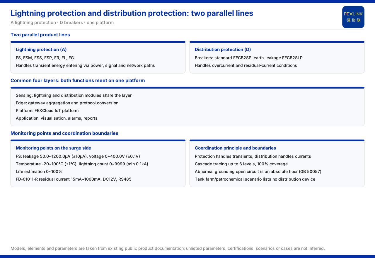
Direct Answer
In the product line overview of the product knowledge base, lightning protection and distribution protection are two parallel product lines, not one category of equipment that can substitute for the other. The intelligent lightning-protection side includes the surge protective device monitor, the intelligent lightning-protection monitoring terminal, the intelligent surge protective device, the SPD lightning-protection base, the grounding resistance monitor, the lightning current / transient current monitor, and the lightning-protection smart gateway; distribution protection is the standard and residual-current intelligent breakers. The two lines serve two different functions, surge protection and overcurrent/leakage protection.
Configuring lightning protection therefore does not mean distribution protection can be omitted, and vice versa. The relationship is one of cooperation: lightning protection handles transient energy intruding along power, signal, and network paths, while distribution protection handles normal and fault currents such as overcurrent and residual current. The four-layer architecture places both types of monitoring at the same perception layer, aggregated through the same platform, showing architecturally that they should work together rather than replace each other. This article sets out their functional boundary, monitoring locus, and cooperation method.
I. The Two Product Lines Are Parallel in the Overview
The product line overview groups intelligent lightning protection as one category, bringing in the surge protective device monitor, the intelligent lightning-protection monitoring terminal, the intelligent surge protective device, the SPD lightning-protection base, the grounding resistance monitor, the lightning current / transient current monitor, and the lightning-protection smart gateway; the intelligent breakers (standard and residual-current) are grouped under the breaker category. The two sit in parallel positions on the map, showing they are two product lines managed separately.
This parallel relationship matters. Treating them as the same type makes it easy to pick only one in a plan — for example, believing that having a breaker removes the need for lightning protection, or that having lightning protection removes the need for distribution protection. The product-line division itself signals that their protected objects and operating mechanisms differ and should be considered separately, then coordinated at the scheme level.
II. Four-Layer Architecture: Two Functions Meet on One Platform
The knowledge base gives the general four-layer architecture of the monitoring system: perception layer, edge layer, platform layer, and application layer. The perception layer carries front-end acquisition, including monitoring modules, smart meters, and sensors, among which are lightning-oriented monitoring and components such as Rogowski coils, NTC, and microamp-level leakage current sensors; the edge layer consists of the lightning-protection smart gateway, the intelligent edge-computing gateway, the industrial gateway, the industrial wearable, and the cloud PLC, carrying protocol conversion, edge computing, and local buffering; the platform layer is the IoT cloud platform; and the application layer provides operations-oriented visualization and management functions.
Placing lightning and distribution monitoring at the same perception layer means data from both sides are acquired in parallel at the source and aggregated through the same platform. The architecture ranks neither above the other; it brings the data of the two functions together for correlation analysis, so when an anomaly involves both surge and distribution the platform can look at evidence from both sides together.
III. Monitoring Locus on the Surge-Protection Side
Monitoring on the surge-protection side is carried by the surge protective device monitor. The surge protective device monitor (FS series), for example FS-00011-R, has key parameters including leakage 50.0~1200.0μA (±10μA), voltage 0~400.0V (±0.1V), temperature -20~100℃ (±1℃), lightning count 0~9999 (minimum trigger 0.1kA), and life estimation 0~100%. These parameters break the state of surge protection into observable quantities: leakage reflects the protector's own aging trend, voltage reflects the monitored circuit's voltage condition, lightning count records the number of impulses suffered, and life estimation gives the basis for judging whether the protector can continue to carry protection.
Seen together, surge protection is no longer summed up by "whether a protector is installed": whether it has degraded, suffered many impulses, or needs replacement can all be judged from monitoring data. This is why the lightning-protection side needs independent monitoring and platform inclusion.
IV. Monitoring Locus on the Distribution-Protection Side
The distribution-protection side has a corresponding monitoring locus. The knowledge base lists the mains (residual-current) monitoring module, whose representative model is FD-01011-R, which acquires one residual-current channel over 15mA~1000mA, with DC12V power and RS485 communication. Residual current is the quantity related to leakage and insulation on a distribution circuit, and belongs to different physical quantities from the leakage and lightning count on the lightning-protection side.
It should be distinguished that distribution protection is not completed by monitoring modules alone: the intelligent breaker itself performs overcurrent and leakage protection actions, while the residual-current monitoring module provides continuous residual-current data. Monitoring and protection are two levels: protection acts on an anomaly, and monitoring records changes over time. Both levels must be considered when building a cooperative scheme.
V. Grounding: The Shared Bottom Line of Both Functions
Lightning protection and distribution protection both depend on the shared foundation of grounding. The knowledge base lists an abnormal open circuit of the grounding resistance as one of the non-negotiable safety red lines, whose threshold no one may raise, based on the GB 50057 standard. Once grounding is open-circuited, both surge energy and fault current lose their path to earth, and the protection effect of both functions is directly affected.
Grounding monitoring is therefore the shared bottom-line link of both, not an appendage. Including it adds a basic safeguard to both functions; when judging whether a site's protection is complete, besides checking the SPDs and breakers, one should confirm whether grounding is under monitoring.
VI. Interlinked Analysis: Topological Cascading Impact
The cooperation of the two functions is also reflected in the analysis of fault propagation. The knowledge base records that the Wanxiang engine's topological cascading impact capability can trace up to 6 levels of topological influence, with cascading risk coverage of 100%. This means the range over which an event propagates along the electrical topology to multiple levels can be characterized and analyzed.
For both functions this provides a common coordinate: an impulse or fault, whether it first occurs on the power, signal, or distribution path, may propagate along the topology to adjacent levels. Cascading impact analysis lets one judge the affected area and which levels are affected first, correlating the two sides' data rather than viewing each separately.
VII. Configuration Boundaries in a Scenario
In scenarios the two functions' configuration boundaries are also recorded. In the knowledge base's oil-tank farm / petrochemical lightning protection scenario, the recommended combination is explosion-proof grounding resistance monitoring (Ex d IIB), the lightning current / transient current monitor, and the surge protective device monitor. That scenario's recommended combination does not list distribution-protection devices such as intelligent breakers or residual-current monitoring modules.
This record shows that a scenario's recommended combination has its stated scope. If a lightning-protection and explosion-proof project also needs distribution protection, that is added beyond the existing combination, not content the material already recommends.
VIII. Principles of Cooperation
Distilling the above into principles of cooperation: First, distinguish the functions — lightning protection handles transient energy, and distribution protection handles overcurrent and residual current; they cannot substitute for each other. Second, equip monitoring for each — the lightning-protection side collects leakage, voltage, lightning count, and life with the surge protective device monitor, and the distribution side covers residual current and protection actions with the residual-current monitoring module and intelligent breaker. Third, guard the grounding bottom line together, treating grounding monitoring as the shared foundation. Fourth, use cascading analysis for correlation, putting anomalies on both paths into one coordinate system. Fifth, respect scenario boundaries, noting and verifying separately any device added beyond a recommended combination.
Configured by these principles, the two are not an either-or choice but a set that must cooperate, which answers a common puzzle: a breaker does not remove the need for lightning protection, and lightning protection does not remove the need for distribution protection.
Scope and Limits
First, this article restates only the knowledge base's content, and its factual boundary is limited to the product line overview, the four-layer architecture, the surge protective device monitor parameters, the mains (residual-current) monitoring module, the grounding-resistance open-circuit red line, the topological cascading impact, and the typical scenario.
Second, the composition of the product line overview and the four-layer architecture is cited as listed; this article does not add unlisted devices or combinations.
Third, the parameters of the surge protective device monitor and the mains (residual-current) monitoring module are cited as listed; unlisted model specifications are not inferred.
Fourth, the grounding-resistance open-circuit red line and GB 50057 are cited as listed; this article does not expand on the standard's clauses or scope.
Fifth, the 6-level maximum topological cascading and 100% cascading risk coverage are the knowledge base's stated positions; this article only restates them and does not commit to a specific site result.
Sixth, the cooperative configuration must be determined with the site paths, grounding conditions, and project plan; no device list or setting scheme for a specific project is provided.