 微物联研究院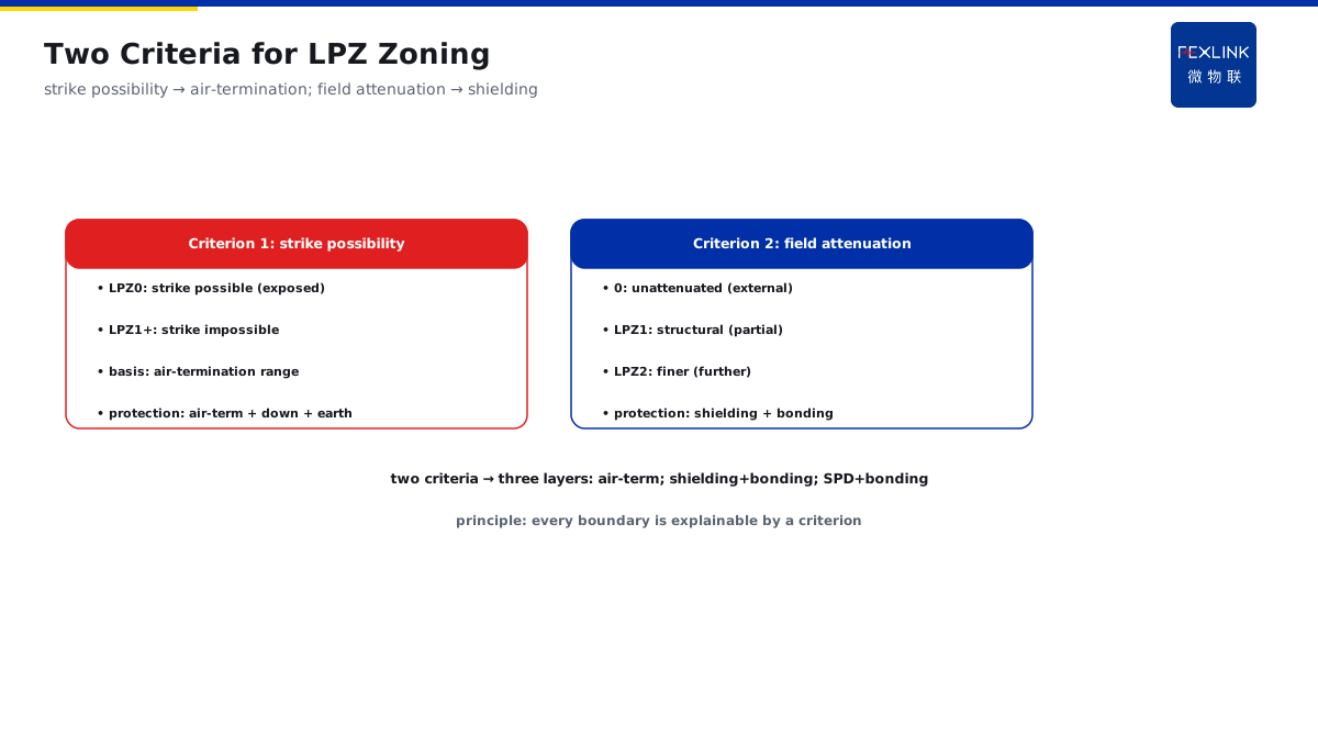
Direct Answer
On design drawings, on what basis are LPZ zones drawn, and what protection is needed at each boundary crossing? The answer: LPZ zones are divided by decreasing "strike probability and electromagnetic-field strength" — LPZ0A is fully exposed (possible direct strike, field unattenuated), LPZ0B is protected by air-termination but the field is still unattenuated, entering the building gives LPZ1 (field attenuated by the structure, no direct strike possible), and deeper areas are LPZ2+; at every zone-boundary crossing, equipotential bonding and a correspondingly rated SPD must be installed to divert surge energy stage by stage.
At one design institute, drawings marked LPZ0B/LPZ1/LPZ2, but on site only one stage of SPD was installed at the main distribution board, and weak-current equipment sat unprotected inside LPZ1. Review pointed out: weak-current equipment should be placed at least in LPZ2, with SPD + bonding at each boundary. After rectification, surge incidents dropped sharply. Zoning core: divide by "can it be struck + how much the field is attenuated"; boundary = SPD + bonding installation position — the deeper the zone, the higher the protection requirement.
Because:
- Two criteria: strike possibility + field attenuation;
- 0A vs 0B: differ in whether air-termination protects;
- Entering the building = entering LPZ1: field attenuated by structure;
- Every boundary needs protection: bonding + correspondingly rated SPDs divert energy stage by stage.
Key insight: "what you do at the boundary" matters more than "what the symbol is called." Every boundary crossing is an SPD and bonding installation position.
At one park, equipment in a machine room was damaged after the thunderstorm season; inspection found the drawings only marked zones with no boundary protection — the main SPD fed weak-current equipment directly (missing the LPZ1→LPZ2 interface). Rectification: add a second-stage SPD + bonding bar at the room entrance. Lesson: zoning is not drawing symbols; it is protection actions at every boundary — missing one boundary misses one protection stage.
1. The Two Criteria for LPZ Zoning
Step one: on what basis are boundaries drawn.
Criterion 1: strike possibility:
- LPZ0 class: direct strike possible (exposed);
- LPZ1 and deeper: direct strike impossible (screened by structure);
- Basis: the protection range of air-termination devices;
- Strike possible → need air-termination + down-conductors (building level).
Criterion 2: electromagnetic-field attenuation:
- 0 class: field unattenuated (external field);
- LPZ1: attenuated by structural shielding (partial);
- LPZ2: further attenuation (finer shielding);
- Basis: structural shielding capability (reinforcement/metal enclosures).
What the two criteria determine:
- Strike possible → air-termination protection (building level);
- Insufficient field attenuation → shielding + bonding (space level);
- Zone boundary → SPD + bonding (line level);
- Three protection layers correspond to the two criteria.
Key insight: "the strike criterion governs air-termination; the attenuation criterion governs shielding" — the two criteria correspond to two protection classes. Zoning is not guesswork; it follows the two criteria.
2. The Key Difference Between 0A and 0B
Step two: zone 0 is split in two.
LPZ0A (fully exposed):
- Direct strike possible;
- Electromagnetic field completely unattenuated;
- Typical positions: roofs, tower tops, open ground;
- Protection: air-termination devices (SPDs cannot block direct strikes).
LPZ0B (protected by air-termination):
- Within the air-termination protection range;
- Direct strike impossible (protected by mesh/rods);
- But the field is still unattenuated;
- Typical position: roof equipment under the air-termination mesh.
The difference:
- Differs in "whether air-termination protects";
- Same: field unattenuated;
- 0A needs air-termination (against direct strikes);
- 0B needs none (already protected) but must guard against induction.
Key insight: "0A guards against direct strikes; 0B guards against induction" — the same zone has two halves with different priorities. 0B equipment looks "safe," but field damage still occurs.
3. Why Zone Boundaries Are the SPD and Bonding Installation Positions
Step three: what goes on the boundary.
The meaning of zone boundaries:
- Points of field-strength step change (attenuation steps);
- Points where surge energy must be diverted stage by stage;
- Connection points where potential must be equalized;
- Boundaries where protection ratings must match.
What to do at the boundary:
- Equipotential bonding (equalize conductors crossing zones);
- Install SPDs (matching rating and discharge capacity);
- Shielding continuity (shield layers grounded across zones);
- Standard cabling (treatment where cables cross boundaries).
Why stage by stage:
- One-time discharge carries too much energy (equipment cannot withstand);
- Stage-by-stage diversion (energy decreases to equipment tolerance);
- Inter-stage coordination (upstream acts first, downstream does not trip randomly);
- Protection-range continuity (no protection blind spots).
Key insight: "boundary = bonding + SPD installation position" — install one stage per boundary crossed. Miss one boundary, miss one protection stage.
4. A Building Section Stacking Zones, Air-Termination, Down-Conductors, and SPDs
Step four: look at it in combination.
Section elements:
- Air-termination devices: roof (protecting the 0B zone);
- Down-conductors: along the building (entry path);
- Earthing grid: at the bottom (current discharge);
- Zones: 0A (outside) → 0B (under air-termination) → 1 (indoor) → 2 (core).
Section mapping:
- 0A: exposed area above the roof;
- 0B: roof equipment under the air-termination mesh;
- LPZ1: indoor (attenuated by structural shielding);
- LPZ2: machine room/core equipment (further shielding);
- Boundaries: SPD + bonding at the entrance and room entrance.
Protection stacking:
- Building level: air-termination + down-conductors + earthing (against direct strikes);
- Space level: shielding + zoning (against induction);
- Line level: boundary SPDs (against wave invasion);
- Three levels stacked = complete lightning-protection system.
Key insight: "the section = zones + air-termination + down-conductors + SPDs in one drawing." Design with the four elements stacked; protection then leaves no gaps.
5. Zoning Design vs. GB 50343 Electronic-Information-System Classification
Step five: how the code maps.
GB 50343 classification:
- Classify electronic-information systems by importance (A/B/C levels);
- Corresponding protection requirements;
- Level A (critical systems) requires higher protection;
- Deeper zoning, higher level, stricter protection.
Zoning vs. classification mapping:
- High-level systems: place in LPZ2 or deeper;
- Critical equipment: multi-stage SPDs across multiple boundaries;
- General equipment: inside LPZ1 + boundary SPDs;
- Classification determines zone depth and SPD stages.
Code implementation:
- Set the system level before design;
- Draw LPZ zones by level;
- Configure boundary protection by level;
- Verify protection completeness at acceptance.
Key insight: "system classification → zone depth → SPD stages" is a consistent chain. The code's classification is the "rating table" for zoned protection — set the level first, then draw the zones.
6. Product Landing: Intelligent Lightning-Protection On-Line Monitoring
FEXLINK products land zoned protection:
- FSS Intelligent Surge Protective Device: boundary SPDs at every stage (status indication + thermal disconnector);
- FS SPD Monitor: SPD state and leakage trend (boundary-protection effectiveness);
- Platform: SPD states at every stage + lightning events + trend analysis;
- Zoned protection + monitoring verification — protection state visible.
Design principle in one sentence: "zone by criteria, protect at every boundary, rate SPDs by level." Clear zoning, complete boundary protection — surges diverted stage by stage, equipment safe.
7. Common Design Misconceptions
- Marking symbols without installing protection: zones drawn, no boundary SPDs on site. Consequence: zoning is a formality. Correct: install SPD + bonding at every boundary.
- One-stage SPD to the end: thinking one stage at the main board suffices. Consequence: energy not diverted stage by stage. Correct: staged installation + inter-stage coordination.
- Treating 0B as a safe zone: assuming no risk under air-termination. Consequence: induction damage. Correct: 0B guards against induction (shielding + SPD).
- Zoning disconnected from classification: drawing zones without system level. Consequence: mismatched protection levels. Correct: set the level first, then zone.
- Ignoring bonding: installing only SPDs at boundaries. Consequence: potential-difference strikes. Correct: SPD + bonding together.
Scope and Limitations
This article explains the LPZ lightning-protection zoning basis (LPZ0A/0B/1/2) and boundary-protection requirements, applicable to lightning-protection design and construction-drawing review. Specific zone boundaries must follow building structure, air-termination arrangement, and shielding capability; SPD selection and inter-stage coordination require professional design per GB 50343/GB 50057 and other codes; system classification (A/B/C) determines protection depth. All cases are anonymized (a certain design institute/a certain park) and do not refer to any specific customer.