 微物联研究院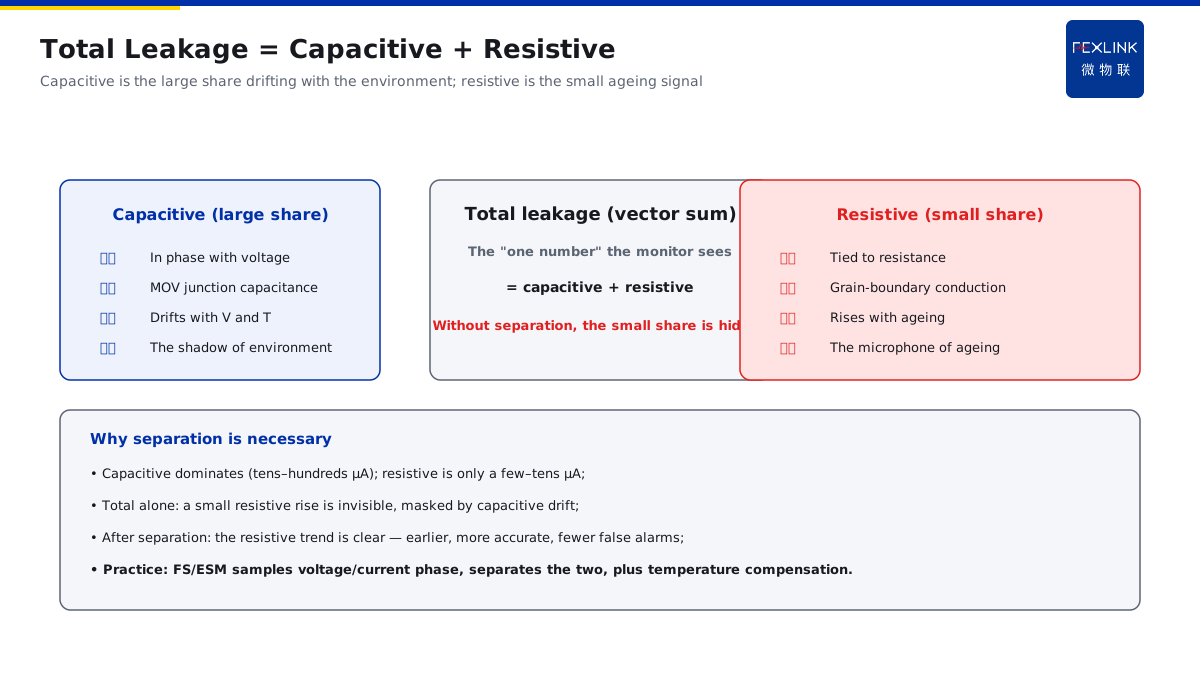
Direct Answer
Of the leakage current measured online on an SPD, how much is normal and how much is the real signal of MOV ageing? The answer: the SPD leakage consists of a capacitive component roughly in phase with the voltage and a resistive component tied to the resistance; the capacitive part drifts normally with grid voltage and temperature, while the resistive part rises significantly only as the MOV ages (grain-boundary breakdown, developing leakage paths). Separating the resistive component and watching its trend detects degradation earlier and more accurately than watching total leakage, and it also reduces false alarms.
At a distribution room, a total-leakage threshold alarm on one SPD kept tripping during the summer as the total drifted past the threshold; bench-testing with a resistive-current tester showed the resistive component had only risen slightly and the MOV was not degraded. After switching the monitoring to resistive-component trend judgment, the false alarms stopped, and another SPD that was truly ageing was caught early. The key distinction: total leakage = capacitive + resistive — the capacitive part drifts normally with the environment, and a rising resistive part is the real ageing signal; looking at the total lets temperature and voltage mislead you, while separating the resistive component gives a true reading.
Why:
- Two components: the capacitive part is roughly in phase with the voltage (normal); the resistive part is tied to the resistance (ageing signal);
- Why the capacitive part drifts: the MOV junction capacitance changes with voltage and temperature — normal fluctuation;
- How ageing shows up: grain-boundary breakdown and developing leakage paths → a significant rise in the resistive component;
- μA-level precision: the two components often differ by only tens of μA; without enough precision you cannot separate them.
Key insight: "The capacitive component is the shadow of the environment; the resistive component is the microphone of ageing — separate it and watch the trend to catch degradation earlier and more accurately."
At a data centre, total leakage was recorded monthly and stayed flat for a year, triggering no alarm; a routine check with a resistive-current analyser found the resistive component had been rising for three consecutive months, near the knee point. After replacing the SPD, the resistive component fell back. Lesson: a flat total can mask a quietly rising resistive component — only separation leaves ageing nowhere to hide.
1. The Two Components of Total Leakage: Capacitive vs Resistive
Step one: leakage is not "one number".
The capacitive component (the larger share):
- The MOV behaves capacitively (junction capacitance);
- The current leads the voltage by about 90°;
- Its magnitude varies with voltage and temperature;
- It is always present in normal operation.
The resistive component (the smaller share):
- The MOV grain boundaries conduct resistively;
- The current is roughly in phase with the voltage;
- Its magnitude rises significantly with ageing;
- It is the "sensitive indicator" of degradation.
Why separate them:
- Total leakage = capacitive + resistive (vector sum);
- The capacitive component masks the resistive change (larger share);
- Looking at the total alone, a small resistive rise is invisible;
- After separation, the resistive trend becomes clear.
Key insight: "Leakage is the sum of two vectors — the capacitive part is large, the resistive part small; without separation, the small part's deterioration is hidden by the large part."
2. Why the Capacitive Component Drifts with Voltage and Temperature
Step two: why environmental changes make the total "lie".
The effect of voltage:
- Grid voltage fluctuates (±10% is normal);
- The MOV junction capacitance changes with voltage;
- The capacitive leakage follows the voltage;
- Higher voltage → higher leakage (not ageing).
The effect of temperature:
- Higher temperature → higher leakage;
- The junction capacitance has a temperature coefficient;
- Summer leakage is generally higher;
- The temperature effect is easily confused with ageing.
Effect on the total:
- The total drifts "normally" with the environment;
- Threshold alarms mis-operate (in summer);
- Real ageing is masked by the drift;
- The total alone cannot distinguish.
Key insight: "The capacitive component follows voltage and temperature — a summer 'leakage exceedance' may just be heat, not damage."
3. How MOV Ageing Shows Up in the Rising Resistive Component
Step three: the physical process of ageing.
MOV ageing mechanism:
- Grain boundaries degrade under long-term voltage stress;
- Boundaries break down, forming leakage paths;
- The resistive leakage increases;
- Path expansion → accelerated ageing (thermal-runaway risk).
Behaviour of the resistive component:
- Early ageing: small resistive rise (below threshold);
- Mid-stage: continuous rise (clear trend);
- Late stage: significant increase (near end of life);
- The resistive rise precedes any "perceptible" change in the total.
Why "earlier":
- The resistive share is small; early changes do not affect the total's appearance;
- After separation, tiny rises can be identified as a trend;
- Early detection → early replacement;
- Avoid developing into thermal runaway.
Key insight: "Ageing starts at the grain boundaries — the resistive component is a direct reading of the boundary state; a rising trend is ageing speaking."
4. What Separating the Resistive Component Means for Fewer False Alarms
Step four: fewer false alarms, earlier detection.
Sources of false alarms:
- Total-leakage threshold + environmental drift → summer false alarms;
- False alarms make operations "cry wolf";
- Widening the threshold → real ageing is missed;
- A dilemma.
The resistive-component approach:
- Watch only the resistive trend, not the capacitive fluctuation;
- Environmental drift does not trigger (normal fluctuation filtered);
- Real ageing must trigger (rising trend);
- Fewer false alarms and fewer missed detections.
Engineering effect:
- More accurate alarms (less manual review);
- Earlier ageing detection (a wider replacement window);
- More credible data (the trend is explainable);
- Operations focus on real problems.
Key insight: "Separating the resistive component filters out environmental noise and amplifies the ageing signal — fewer false alarms, yet earlier detection."
5. Why Online Monitoring Needs μA-Level Precision to Separate the Two
Step five: measurement precision is the precondition for separation.
Why it is hard:
- The capacitive component is the main quantity (tens to hundreds of μA);
- The resistive component is small (a few to tens of μA);
- Both are summed in the total leakage;
- Without enough precision, separation is impossible.
μA-level precision:
- Requires synchronously sampling the voltage and current phase;
- Computes the in-phase component (resistive) and the quadrature component (capacitive);
- μA-level resolution is needed to recognise early changes;
- This is the technical precondition for "separation".
Engineering requirements:
- Sensor range and resolution matched;
- Phase synchronisation (voltage reference);
- Temperature compensation (distinguish environment from ageing);
- Trend algorithms (baseline + knee point).
Key insight: "You can only separate what you can measure — without μA-level precision and phase synchronisation, the resistive component is invisible."
6. Product Implementation: Intelligent Lightning-Protection Online Monitoring
WeiWuLian products put resistive separation into practice:
- FS/ESM SPD Monitor: synchronously samples voltage/current phase and separates capacitive/resistive components;
- FSS Intelligent SPD: built-in monitoring with self-diagnosis;
- Platform trend analysis: resistive-component baseline + knee-point alarms;
- Temperature compensation: filters environmental drift and reduces false alarms.
The design principle in one sentence: "Separate the resistive component, watch the trend, set the knee point — ageing detected earlier, false alarms greatly reduced."
7. Common Misjudgments
- "Total-leakage exceedance means ageing": summer capacitive drift also exceeds. Result: frequent false alarms. Correct: judge by the separated resistive component.
- "A flat total means safe": the resistive part rises quietly and is masked. Result: ageing missed. Correct: track the resistive trend.
- A fixed threshold on the total: not corrected for the environment. Result: a dilemma (false/missed alarms). Correct: resistive trend + knee point.
- "Leakage measurement" without phase synchronisation: the two parts cannot be separated. Result: the measurement is useless. Correct: μA-level + phase separation.
- No temperature compensation: environmental drift treated as ageing. Result: unreliable alarms. Correct: compensate, then watch the trend.
Scope and Limitations
This article explains the capacitive/resistive composition of SPD leakage, why the capacitive part drifts with the environment, the principle of the resistive component as an MOV-ageing signal, and the value of separation for fewer false alarms, applicable to SPD online-monitoring selection and data interpretation. The quantitative threshold and knee point of the resistive component depend on the SPD type, manufacturer data and on-site voltage/temperature; follow GB/T 18802.11 and the product manual, determined by professional operations. All cases are anonymized (a distribution room, a data centre) and do not refer to any specific customer.