 FEXLINK Research Institute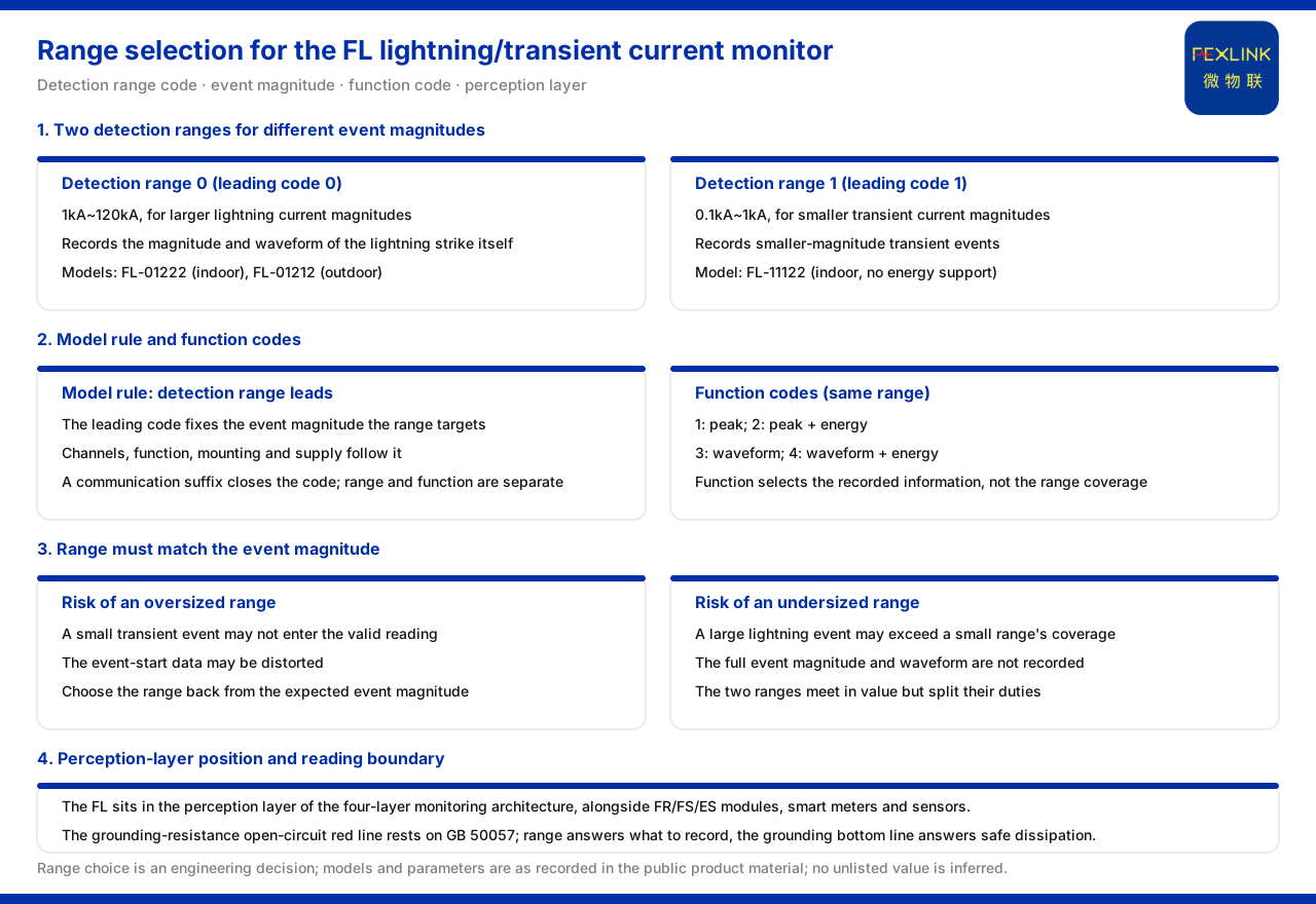
Direct answer
The two detection ranges of the FL lightning current / transient current monitor (e.g. FL-01222) correspond to events of different magnitudes: detection range 0 is 1kA to 120kA, aimed at larger-magnitude lightning currents; detection range 1 is 0.1kA to 1kA, aimed at smaller-magnitude transient currents. Which range to choose depends on whether what must be recorded is the main lightning discharge itself or a lower-magnitude transient disturbance. The knowledge base distinguishes the two ranges by the first model digit and provides different function combinations such as peak, energy and waveform under the same range. The knowledge base does not give a decision rule for "which range a given site must choose"; the range understanding and selection order in this article are an application-layer extrapolation.
Model rule and the two ranges
The knowledge base specifies that the FL model rule is FL plus detection range, channel count, function, installation method and power position, ending with a communication suffix, with the detection range as the first digit determining the event magnitude the range faces. Detection range 0 is 1kA to 120kA, aimed at larger-magnitude lightning current; detection range 1 is 0.1kA to 1kA, aimed at smaller-magnitude transient current. When reading a model, look at the first digit to judge the event magnitude the meter faces. Since the detection range comes first, it is also the segment to determine first during selection.
Correspondence between magnitude and event type
Placed together, 1kA to 120kA covers the current magnitude a main lightning discharge may reach; 0.1kA to 1kA covers a lower-magnitude transient current. The two are numerically close end to end, but their uses are clearly divided: the former records the magnitude and waveform parameters of a lightning event itself and can serve as the event origin of topological cascade tracing; the latter records smaller-magnitude transient events. Choosing a range is essentially deciding how large an event must be recorded, then determining whether the range coverage fits. If the range is too large, small events may not enter valid readings; if too small, large events may exceed coverage. Range selection should therefore return to the expected event magnitude.
Function codes
The FL function codes given by the knowledge base are: 1 for peak, 2 for peak plus energy, 3 for waveform, and 4 for waveform plus energy. This shows that under the same range, different event details such as peak, energy or waveform can be recorded: function 1 suffices when only the peak is needed; a function including energy is chosen when energy must be assessed; a function including waveform is chosen when the waveform must be reproduced. The function code determines the type of information recorded under the same range and does not change range coverage; therefore range and function can be determined separately, range first and function second. Understanding these functions by recording purpose is clearer: peak answers "how high at most", energy answers "how large cumulatively", and waveform answers "what the process looks like". If an interpretation only needs to judge whether a larger event occurred, peak information is often enough; to assess the destructive energy of an event, a function including energy is needed; to reproduce the process for in-depth analysis, a function including waveform is needed.
Why the event origin must choose the right range
In the context of level tracing, lightning-current monitoring plays the role of event origin. The knowledge base uses the peak and energy monitoring capability corresponding to detection range 0 to record the magnitude and waveform parameters of a lightning event itself. If the range does not match the event magnitude, the event-origin data may be distorted: a lower-magnitude transient event may not be enough to trigger valid readings of a large range, and a larger-magnitude strike may exceed the coverage of a small range. Choosing the right range is therefore the precondition for usable event-origin data; this also explains why the detection range is placed first in the model rule.
Model comparison
The knowledge base model table lists: FL-01222 as indoor, AC220V, peak 1kA to 120kA, energy supported; FL-01212 as outdoor, AC220V, peak 1kA to 120kA, energy supported; FL-11122 as indoor, AC220V, peak 0.1kA to 1kA, energy not supported. The three correspond to typical configurations of detection ranges 0 and 1: the two range-0 models support energy monitoring and the one range-1 model does not. In form, the knowledge base records that the FL uses a lightning-protection monitoring enclosure (white or black), of which the FL-01212 outdoor model is an aluminum enclosure of 204×202×72mm.
Its place in the system
The knowledge base lists the FL lightning current / transient current monitor in the perception layer of the general four-layer architecture of the monitoring system, on the same level as FR, FS and ES-series monitoring modules, smart meters and sensors (Rogowski coil, NTC, microamp-level leakage-current sensor). The perception layer handles acquisition, and the edge layer handles protocol conversion and local caching. Understanding range selection should also place it back in the perception layer: the range determines what magnitude of event is acquired, and subsequent aggregation and analysis build on this acquisition convention. If the acquisition convention does not match the event magnitude of interest, subsequent analysis can hardly reconstruct the event itself.
Order for choosing a range
Following the above, first judge the event magnitude to be recorded: choose detection range 0, i.e. 1kA to 120kA, for the magnitude of a main lightning discharge; choose detection range 1, i.e. 0.1kA to 1kA, for lower-magnitude transient current. Then choose the function code according to the event detail needed and choose an indoor or outdoor model according to the installation environment. The knowledge base does not give a decision rule for "choosing a range by which field conditions"; this trade-off is an engineering decision that should be determined together with field event characteristics and historical records. For existing projects, the range can also be estimated by referring to event magnitudes already recorded at similar sites. If a site has both large-magnitude and small-magnitude events to track, monitoring devices of the corresponding range can be configured separately by event type, rather than trying to cover all events with a single range.
Coordination with the grounding baseline
The knowledge base records that the grounding-resistance abnormal open-circuit red line is based on GB 50057, and once triggered no one can raise the threshold. The event magnitude recorded by lightning current and transient current monitoring must be understood in coordination with grounding, the standard baseline link: even if a lightning event is recorded, it must also be confirmed whether the grounding path is intact. The range answers "how large an event is recorded" and the grounding baseline answers "whether it enters the earth safely"; together they form a complete interpretation of one lightning event. In the same system, range selection and grounding monitoring belong to different acquisition items of the perception layer, and their data can be merged for interpretation after aggregation at the gateway, bringing event magnitude and grounding state into the same framework for verification.
Scope and limitations
- The detection ranges, function codes, models and form in this article are limited to the existing records of the knowledge base, and do not introduce standard clauses or decision thresholds not listed there.
- The knowledge base does not define a decision rule for "which sites must choose detection range 0 or 1"; the selection order in the text is an application-layer extrapolation.
- The models and parameters in the text are existing records of the material, and no specification or monitoring effect of unlisted models is inferred from them.
- Actual selection and interpretation must be verified by the engineering party together with field event characteristics and design conventions; this article does not provide calculation results for range selection.