 FEXLINK Research Institute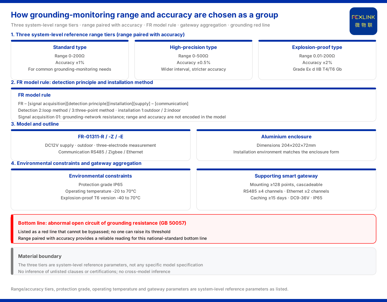
Direct answer
Choosing the range for grounding monitoring is in essence letting the measurement interval of the device cover the resistance range of the monitored grounding network while meeting the required accuracy and environmental conditions. In the system-level reference parameters of the grounding resistance monitoring system, the product material gives three monitoring-unit tiers: the standard type is 0-200Ω (±1%), the high-precision type is 0-500Ω (±0.5%), and the explosion-proof type is 0.01-200Ω (±2%) with an Ex d IIB T4/T6 Gb explosion-proof grade. These three tiers show that range and accuracy are configured as a group; one should not look at the range number alone but choose as a group according to the resistance range and accuracy requirement of the monitored grounding network. The material also specifies a protection grade of IP65 and an operating temperature of -20 to 70℃, with -40 to 70℃ for the explosion-proof T6 version — system-level constraints to be satisfied together with the range.
1. Range and accuracy must be viewed as a group
The most common deviation in choosing a range is to take "the larger the range the better" as a default principle. The three tiers given by the material are precisely the opposite: range and accuracy are bound into a group, with the standard type covering 0-200Ω at an accuracy of ±1% and the high-precision type covering 0-500Ω at an accuracy of ±0.5%. The high-precision type is not only wider in range but also stricter in accuracy; the explosion-proof type pushes the range down to 0.01Ω and up to 200Ω, with an accuracy of ±2%, plus an explosion-proof grade.
This shows that range is not an isolated number but one item in a set of matching indicators. First confirm roughly in which interval the resistance of the monitored grounding network falls, then confirm how large a measurement deviation the scenario can accept, and the range tier will emerge naturally. If only the upper range limit is considered, one may choose a tier wide enough in range but not meeting the accuracy requirement, or the reverse.
2. The applicable emphasis of the three system-level reference ranges
Listing the three tiers side by side means that different scenarios have different emphases. The standard type faces common grounding-monitoring needs, and the interval of 0-200Ω with an accuracy of ±1% forms a general baseline. The high-precision type faces scenarios with a higher accuracy requirement and a wider resistance interval, and the combination of 0-500Ω with ±0.5% goes a step further in both coverage and reading stability. The explosion-proof type faces occasions needing an explosion-proof configuration and, besides a range and accuracy set of its own, carries an Ex d IIB T4/T6 Gb explosion-proof grade.
The explosion-proof type especially needs attention: it is not a matter of simply moving conventional equipment into a hazardous environment but of having a dedicated range, accuracy and explosion-proof convention. Occasions needing an explosion-proof configuration should choose from this tier and must not substitute the parameters of a conventional tier. It should be noted that these three tiers are system-level reference parameters and are not equivalent to the specification of any specific model.
3. How the model rule carries the detection principle and installation method
Beyond the range, the detection principle and installation method also enter the model. The model rule given by the material for the FR grounding resistance monitor (e.g. FR-01311-R) is FR–[signal acquisition][detection principle][installation method][supply]–[communication]. Within it, detection principle 2 is the loop method and 3 is the three-point method; installation method 1 is outdoor and 2 is indoor; signal acquisition 01 corresponds to the grounding-network resistance.
The detection principle decides in what way the measurement is connected, and the installation method decides whether the device is configured for indoor or outdoor environment; both are fixed at the selection stage rather than decided on the fly on site. It is worth noting that range and accuracy are not encoded in the model rule and need to be chosen separately against the system-level parameters. That is, the model body answers "how it measures, where it is installed, how it is supplied and how it communicates", while "how large a range and how much accuracy it measures" must return to the system-level reference parameters for matching.
4. Specific models and outline
The model table of the material lists three communication configurations of the series, taking FR-01311-R as an example: the three are all supplied at DC12V, installed outdoors and measured by the three-electrode method, and their communication is respectively RS485, Zigbee and Ethernet. The outline is an aluminium enclosure with dimensions 204×202×72mm. The same model body distinguishes the uplink method by suffix, showing that the communication field is an independent option. This also reminds us that the same detection principle and installation method of the model body do not mean the communication can be specified at will; the communication suffix must correspond to the uplink method actually available on site.
5. Multi-point grounding networks and gateway capability
Range selection must also be planned together with aggregation capability. The material gives the system-level parameters of the supporting smart gateway: mounting no fewer than 128 points and being cascadeable, no fewer than 4 RS485 channels, no fewer than 2 Ethernet channels, optional 4G, 5G and LoRa, data caching no fewer than 15 days, a DC9-36V wide-voltage supply and an IP65 protection grade.
When one grounding network needs several measuring points, the gateway's mounting points, serial and network ports, and caching days determine how many measuring points can be connected and how long data can be preserved during a network outage. The range decides how large a span each point can measure, while the gateway and platform are responsible for aggregating the data of the scattered points. Therefore, a multi-point scenario should plan range selection and gateway mounting and communication capability on the same table, rather than fixing the devices first and adding the gateway afterwards.
6. The selection meaning suggested by the application scenarios
The material notes that this class of grounding resistance monitor has been applied to such projects as online monitoring of the grounding network of railway traction substations and port tank farms (10 sets per tank). These applications give two hints: first, the grounding network is distributed in points, with one monitoring unit configured per point and then aggregated and uplinked through the gateway; second, the point density differs greatly between scenarios, and the tank farm arranges points per tank, showing that the number of measuring points can be sizable and systematic.
Precisely because the scenarios differ markedly, range selection must return to the resistance range and point density of the monitored grounding network itself rather than applying a uniform tier. The resistance range decides the range and accuracy tier, and the point density decides the gateway mounting and communication planning; together they form the basis of selection.
7. Bottom line: an abnormal open circuit of grounding resistance
Whichever range tier is chosen, one bottom line does not change. The material lists "an abnormal open circuit of grounding resistance" as a red line that cannot be bypassed, whose threshold no one can raise, with GB 50057 as the basis standard. The choice of grounding-monitoring range and accuracy therefore ultimately serves this non-relaxable national-standard bottom-line judgement.
This also shows that the range is not safer the wider it is: only when the device can first read and read accurately the grounding resistance does the red-line criterion have a usable data basis. The matching of range and accuracy is precisely what provides a reliable reading for this bottom line.
Scope and limitations
First, this article explains only how to choose range tiers such as 0-200Ω and 0-500Ω for grounding monitoring; the factual boundary is limited to what the product material lists, and it introduces no standard clause, parameter, certification or case not listed.
Second, the 0-200Ω (±1%), 0-500Ω (±0.5%) and 0.01-200Ω (±2%, Ex d IIB T4/T6 Gb) are all system-level reference parameters listed by the material; this article does not equate them with the specification of any specific model, nor does it judge whether on-site grounding resistance is acceptable on that basis.
Third, the protection grade, operating temperature, gateway mounting and caching parameters, and the application records such as railway traction substations and port tank farms, are all existing records of the material; this article makes no cross-model inference and extends no unrecorded quantitative effect.
Fourth, the reference to GB 50057 in this article is limited to the grounding red-line criterion recorded in the material and does not expand the specific clauses of that standard; the final choice of range and accuracy must be verified in conjunction with on-site grounding-network conditions.