 FEXLINK Research Institute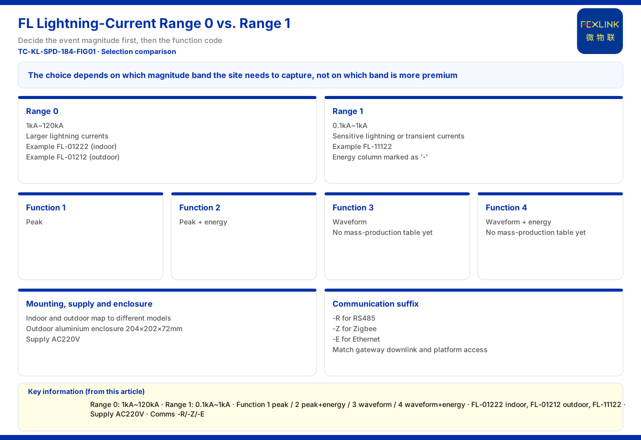
Direct answer
The two detection ranges of the FL lightning current / transient current monitor divide the work by current magnitude: range code 0 is 1kA to 120kA, for relatively large lightning currents, and range code 1 is 0.1kA to 1kA, for relatively sensitive lightning or transient currents. The core basis for choice is which magnitude band the site wants to capture, not which band is more high-end. Note that the product material lists only these two ranges and does not give a mandatory binding between a range and a specific scenario, nor an on-site current estimation method; selection should therefore return to the magnitude of the event the site intends to record.
1. What the two detection ranges cover
The detection range codes given by the product material are: 0 corresponds to 1kA to 120kA, and 1 corresponds to 0.1kA to 1kA. The former is wide with a high upper limit, suitable where larger lightning currents are the concern; the latter is narrow but has a low lower limit, suitable where smaller-magnitude transient currents are the concern. The gap between the two bands, around 1kA, means that before selection one must first establish roughly which magnitude the measured event falls into; otherwise a deviation arises in which the event is either not captured or not measured accurately. Understanding this division of ranges is the precondition for the later choice of model and function tier.
2. The detection-range digit in the model sets the magnitude
In the product material, the model code of the FL lightning current / transient current monitor (e.g. FL-01222-R) includes a detection-range digit. Taking the FL-01222 series as an example, its peak value is 1kA to 120kA, belonging to range code 0, while the FL-11122 series has a peak value of 0.1kA to 1kA, belonging to range code 1. This means selection does not require memorising anything by rote: lock the code digit according to the magnitude the site needs, then add the installation, supply and communication suffixes to arrive at the corresponding model. The product material also gives the FL-01222 as an indoor version and the FL-01212 as an outdoor version; both support 1kA to 120kA and both support energy recording, and the outdoor version has an aluminium case measuring 204×202×72mm, which can be checked when arranging the site.
3. Within the same magnitude, choose a function tier
Once the detection range is fixed, it remains to confirm which current features need to be recorded. The function codes in the product material are: 1 for peak, 2 for peak plus energy, 3 for waveform, and 4 for waveform plus energy. That is, within the same detection range, the function tier determines the recording dimension. Taking a common model in range code 0, the FL-01222 and the FL-01212 both support energy recording, while the FL-11122 in range code 1 marks the energy column with a dash, indicating that its recording dimension differs from the former. Selection should first establish whether peak, energy or waveform is needed, then check the function digit of the model, to avoid the situation where the range is right but the recorded content is insufficient. The product material also notes that the waveform tiers (functions 3 and 4) do not yet have a mass-production selection table.
4. Choose by the event magnitude the site wants to capture
The product material's recommended combination for the oil-tank-area and petrochemical lightning-protection and explosion-proof scenario includes FL lightning current monitoring, which shows that in an explosion-proof scenario needing simultaneous collection of lightning-current magnitude, lightning-current monitoring is part of the combination. This clue can be used to understand the selection logic: first see whether the site cares more about large-current lightning events or smaller-magnitude transient events, then choose the range code accordingly. If the site has both a large-current recording need and a wish to cover small-magnitude events, it should be recognised as two collection needs of different magnitudes to be checked separately, rather than assumed that one range covers everything by default. The product material gives no rule binding a scenario to a range, so the final judgement must still combine the site's actual focus on event types.
5. Split range and function into two questions
The most common selection mistake is to conflate the detection range and the function tier into one question. The more robust approach is to split them into two: first, is the event magnitude the site wants to record mainly above or below 1kA; second, besides the peak, is energy or waveform also needed. The first question determines the detection-range code and the second the function code. Once both are answered, the remaining digits of the model, namely installation, supply and communication, become meaningful. In the product material, the FL-01222 and FL-01212 in range code 0 support energy recording, while the FL-11122 in range code 1 marks the energy column with a dash, and such differences show that the two questions cannot be merged. If the site cares only about the peak, function 1 suffices; if the purpose is compatibility assessment of a surge protective device, energy and even waveform are often needed, and the choice of function tier then feeds back on the usable range tier. Answering these two questions before looking at the model table makes the selection process much clearer.
6. Confirm installation, supply and communication together
Beyond the detection range, three further conditions need to be confirmed at the same time. The first is installation: indoor and outdoor versions correspond to different models, and the outdoor version gives an aluminium case dimension for arrangement. The second is supply: common models in the FL series are powered at AC220V according to the product material, and selection must match the on-site power conditions. The third is the communication suffix: FL models offer three communication variants, -R, -Z and -E, corresponding to RS485, Zigbee and Ethernet respectively, which must match the gateway downlink mode and the platform access mode. Confirming range, function, installation, supply and communication separately avoids later adjustments caused by ordering on the basis of range alone. The communication suffix must also correspond to the gateway downlink mode: in the communication protocol matrix given by the product material, the device downlink includes Modbus RTU (RS485) and Zigbee (Modbus), and the uplink includes Modbus TCP and MQTT, which can be used directly for checking that the chosen variant matches the networking mode.
7. Decision rules not given must not be assumed
The product material does not give the decision thresholds or recommended priority by which detection ranges 0 and 1 correspond to specific lightning-current scenarios, nor an on-site current estimation method. One must therefore not infer from the product material that a given scenario must choose a given range, or that a recommended order exists between the two ranges. What selection can do is match the listed ranges against the event magnitude the site cares about, and leave the parts that cannot be determined from the product material alone to the site survey stage for confirmation, rather than setting binding rules by assumption.
Scope and limitations
First, this article explains only the basis for choosing FL detection ranges 0 and 1; the factual boundary is limited to the product material, and no parameter, standard or certification not listed there is introduced; for the mass-production status of the waveform tiers that the material does not elaborate, this article merely notes it and makes no supply judgement.
Second, the ranges, models, supply, installation dimensions and function codes here are as recorded in the product material; this article does not infer the specifications of unlisted models from them.
Third, the product material does not give a mandatory binding between range and scenario; the selection approach here is a method induction from the listed facts and does not represent a decision standard given by the material.
Fourth, the range choice of a specific project must be determined in conjunction with the event type, current magnitude and installation conditions the site focuses on; this article provides no on-site current estimation or selection calculation.