 微物联研究院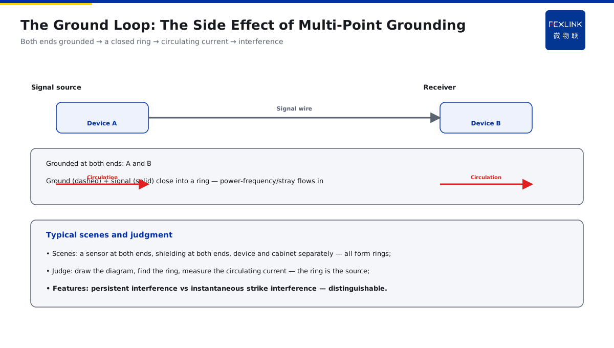
Direct Answer
After adding bonding per the specification, some LV devices now show unexplained interference — was it wired wrong? The answer: bonding itself does not introduce interference; the problem lies in the practice — making a signal loop that should be single-point grounded into a multi-point ground forms a ground loop, or mixing the LV reference ground with the lightning-protection ground introduces power-frequency/stray circulating current. The diagnosis should check whether an extra ground loop has formed, not remove the bonding.
At a monitoring room, after adding bonding per the specification, some devices showed unexplained interference and false operation. Instead of removing the bonding, the practice was checked first: the signal loop was multi-point grounded, forming a ground loop with a power-frequency stray circulating current interfering with the signals. After changing to single-point grounding and clarifying the grounding diagram, the interference disappeared. The key distinction: the interference comes from the ground loop, not the bonding itself — check whether multi-point grounding formed a loop and whether the reference ground was mixed; do not remove the protection measure.
Why:
- The nature of bonding: pulling all metal bodies to the same potential does not introduce interference;
- The ground-loop cause: multi-point grounding of the signal loop forms a ring, with circulating current pouring in;
- The mixing risk: mixing the LV reference ground with the lightning-protection ground brings in power-frequency/stray circulating current;
- The rectification: single-point grounding, isolation, and a clarified grounding diagram.
Key insight: "The interference comes from the ground loop, not the bonding — check the multi-point loop and the reference mixing; rectify with single-point grounding and a clarified diagram; do not remove the bonding."
At a park, LV false operations appeared after bonding; the cause was a signal loop grounded at both ends forming a ring with stray circulating interference. After single-point grounding, it recovered. Lesson: the protection measure is right, the practice is wrong — the ground loop is the interference source.
1. Why Bonding Itself Does Not Produce Interference
Step one: understand the principle of bonding first.
The nature of bonding:
- Pulling all metal/shielding bodies to the same potential;
- Eliminating the potential difference between devices;
- One potential → no difference-driven current;
- It itself does not produce interference.
The difference from earthing:
- Bonding is "connecting";
- Earthing is "connecting to the earth";
- Bonding does not change the discharge path;
- Do not mix the two.
The judgment points:
- Interference after bonding;
- It is not that bonding is "harmful";
- But that the practice introduced a new circuit;
- Check the practice, not remove the measure.
Key insight: "Bonding pulls all metal bodies to the same potential and eliminates the difference — it itself does not produce interference; the interference comes from the practice, not the measure."
2. The Cause of the Ground Loop Formed by Multi-Point Grounding
Step two: check whether a loop formed.
How the ground loop forms:
- The signal loop grounded at both ends;
- The ground wire + signal wire form a closed ring;
- Power-frequency/stray current flows in the ring;
- The interference follows.
Typical scenes:
- A sensor grounded at both ends;
- The shielding grounded at both ends;
- The device and the cabinet grounded separately;
- Multi-point grounding forms a ring.
How to judge:
- Draw the signal-loop grounding diagram;
- Find the closed ring;
- Measure the circulating current in the ring;
- A ring exists → the interference source.
Key insight: "A ground loop = a signal loop grounded at both ends forming a closed ring — power-frequency/stray current flows in it; draw the diagram, find the ring, and there is the source."
3. The Risk of Mixing the LV Reference Ground with the Lightning-Protection Ground
Step three: check whether the reference ground is mixed.
The mixing risk:
- Mixing the LV reference ground (signal ground) with the lightning-protection ground;
- Lightning/power-frequency current enters the reference ground;
- The reference potential is raised/polluted;
- Interference and false operation.
Typical problems:
- The signal ground directly connected to the structural ground;
- The shielding connected to the lightning-protection ground;
- The reference ground mixed with the earthing busbar;
- Circulating current enters the signal circuit.
How to judge:
- Check the signal-ground routing;
- Whether it shares a point with the lightning-protection ground;
- Measure the reference-ground current;
- Mixed → isolate and rectify.
Key insight: "Mixing the LV reference ground with the lightning-protection ground lets lightning/power-frequency enter and pollute the reference potential — check the signal-ground routing; mixed, isolate."
4. The Typical Phenomena of the Ground-Loop Interference
Step four: recognize the interference features.
Typical phenomena:
- Signal fluctuation/drift;
- Intermittent false operation;
- Communication bit errors/packet loss;
- Power-frequency ripple superimposed.
The difference from strikes:
- Strike interference is instantaneous;
- Ground-loop interference is persistent;
- The power-frequency circulating current exists continuously;
- The features are distinguishable.
The check points:
- Whether the interference persists;
- Whether it relates to the load changes;
- Look at the circulating waveform with an oscilloscope;
- Phenomenon → loop → rectification.
Key insight: "Ground-loop interference is persistent (signal fluctuation/bit errors/false operation), while strike interference is instantaneous — the persistence distinguishes them; confirm the waveform with an oscilloscope."
5. Rectification: Single-Point Grounding, Isolation, and a Clarified Diagram
Step five: how to change it.
The rectification principles:
- Single-point grounding of the signal loop;
- Isolate the reference ground from the lightning-protection ground (or follow the specification);
- Single-end grounding of the shielding;
- Clarify the grounding diagram.
The concrete measures:
- Single-point grounding of the sensors/devices;
- Single-end grounding of the shielding (at the signal end);
- Isolate the reference ground from the structural ground;
- Draw and execute a clear diagram.
Practice verification:
- Whether the interference disappears after the change;
- See the earthing state with the FR monitor;
- The diagram matches the reality;
- A data loop; the measure retained.
Key insight: "Rectify in three steps: single-point grounding, reference isolation, clarified diagram — verify the interference disappears; keep the protection measure and do not remove the bonding."
6. Product Implementation: Monitoring and Troubleshooting as One
WeiWuLian products manage bonding troubleshooting:
- FR Earth-Resistance Monitor: online earthing state/resistance;
- Grounding-diagram management: clear circuit routing;
- Loop check: multi-point-loop data;
- Closed-loop verification: interference data comparison after the change.
The design principle in one sentence: "Bonding is right, the practice needs a check — single-point grounding + isolation + a clarified diagram; the FR sees the state online; the interference gone means it is right."
7. Common Misjudgments
- "Bonding is harmful, remove it": confusing the measure with the practice. Result: losing protection. Correct: check the ground loop.
- "Multi-point grounding is more reliable": ignoring the loop. Result: circulating interference. Correct: single-point grounding of the signal loop.
- "The reference ground can go anywhere": ignoring the mixing. Result: potential pollution. Correct: isolate the reference ground.
- "Ground the shielding at both ends": ignoring the single-end principle. Result: the shielding forms a ring. Correct: single-end grounding.
- "No verification after the change": ignoring the loop. Result: the problem remains. Correct: verify and compare the data.
Scope and Limitations
This article explains the troubleshooting of device interference/false operation after adding bonding (the bonding principle, the ground-loop cause, the reference-mixing risk, the typical phenomena and the rectification direction), applicable to troubleshooting interference caused by improper bonding practice. The exact requirements follow GB 50343-2012 and the manufacturers' data; this article explains only the diagnostic logic and rectification points. All cases are anonymized (a monitoring room, a park) and do not refer to any specific customer.