 FEXLINK Research Institute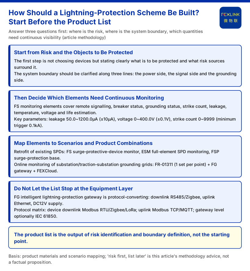
A lightning-protection scheme is often written backwards: first the product list, then the justification. Someone selects the SPDs, decides how many monitoring modules are needed, and only afterwards works out why. The order looks efficient, but it lets the hardware list hide the questions that matter. Each device is supposed to answer something specific, and a sound scheme makes clear what that is and why that particular device is the right choice. A more dependable approach starts with three questions: where is the risk, where does the system boundary lie, and which quantities must be observed continuously. Once those three are fixed, the product list is largely a derived result.
This article follows the sequence risk identification → system boundary → monitoring elements → product mapping. Treat it as a method to be validated against each project.
Reversing the order usually produces two concrete failures. First, once the product list is fixed, a risk review may reveal a point with no sensing means, forcing a costly rearrangement. Second, a list tends to organise itself by model or price rather than by risk priority, so the scheme looks comprehensive but cannot answer which few locations deserve the closest attention. Doing the risk and boundary work first is what makes every later selection explainable and reviewable.
Start from Risk and the Objects to Be Protected
The first step in preparing a scheme is not choosing equipment; it is stating clearly what is being protected and which risk sources surround it. In the knowledge base, the monitoring system is defined as a four-layer architecture — perception, edge, platform and application layers. This layering provides a ready-made checklist: first establish which layers and which stages the monitoring objects of this scheme occupy.
The system boundary should be traced along at least three lines: the power side, the signal side and the grounding side. The boundary is closed only when, for each line, the scheme states where surges originate, which equipment they pass through, and where they are discharged. The knowledge base lists the perception layer as FS/FR/FL/ES series monitoring modules, smart electricity meters, and sensors such as Rogowski coils, NTCs and microamp-level leakage-current sensors. Defining the boundary therefore means deciding which points along those three lines need to be sensed.
Then Decide Which Elements Need Continuous Monitoring
With the boundary clear, the elements can be chosen. Take the FS surge protective device monitor. The monitoring elements listed cover remote signalling, air-switch status, grounding status, lightning-strike count, leakage current, temperature, voltage and lifetime estimation. One device can therefore answer questions on several dimensions at once. The task is not to measure everything measurable but to select according to the risk priorities established in the previous step.
Once elements become parameters, they must be verifiable. The knowledge base gives the key FS parameters as: leakage current 50.0–1200.0 μA (±10 μA), voltage 0–400.0 V (±0.1 V), and lightning-strike count 0–9999 (minimum trigger 0.1 kA). These are the limits the current knowledge base explicitly states; a scheme should not exceed or rewrite them when citing parameters.
Selection should also distinguish outcome quantities from process quantities. Lightning-strike count, for example, records how many surge events have already occurred, whereas leakage current, temperature and voltage are closer to a continuous representation of device state. The two play different roles: the first supports event reconciliation and statistical analysis, the second supports trend observation of condition. Expressing quantities of different natures separately avoids mixing them in one table and lets later alarm rules and response actions attach to the correct measured quantity.
Map Elements to Scenarios and Product Combinations
Only at this stage does the product list appear. The knowledge base provides a scenario → recommended product combination mapping rather than an isolated list of models. For "lightning-protection device condition monitoring (retrofit of existing SPDs)", the recommended combination is the FS surge protective device monitor, ESM full-element SPD monitoring and the FSP lightning-protection base. For "online monitoring of substation / traction substation grounding grids", the recommended combination is FR-01311 (one set per point) plus an FG gateway plus FEXCloud.
The point here is sequence: scenarios and elements come first, combinations afterwards. The same set of elements may combine differently in different scenarios, and a combination's credibility comes from whether it answers the risk questions raised in the first step, not from the length of the list. Each role in a combination should also be stated clearly: ESM is positioned as an all-element SPD monitoring terminal, FSP as an SPD lightning-protection base, and FR-01311 as a grounding-resistance monitoring unit configured at one set per point. Where specific models and names are used, the terminology locked in the knowledge base should be applied consistently: FS = surge protective device monitor, ESM = intelligent lightning-protection monitoring terminal (SPD monitor), FR = grounding resistance monitor, FL = lightning current / transient current monitor, FG = lightning-protection intelligent gateway, SPD = surge protective device.
Do Not Let the List Stop at the Equipment Layer
The product list is an intermediate product. It must still answer how data gets out and where it goes. The FG lightning-protection intelligent gateway is defined in the knowledge base as a protocol-conversion type, with downlink support for RS485 and Zigbee and uplink support for Ethernet, powered at DC12V, in models FG-0221-ER and FG-0221-EZ. Communication capability follows the protocol matrix: device downlink includes Modbus RTU (RS485), Zigbee (Modbus) and LoRa; device uplink includes Modbus TCP / MQTT (Ethernet, 4G); at gateway level, IEC 61850 is optional. Against the four-layer architecture, the perception and edge layers handle "sense it and transmit it", while the platform and application layers handle "see it and judge it". A scheme must specify the gateway and uplink choices at this point; otherwise even a complete set of devices cannot close the loop.
Boundaries and Limitations
Several limitations bear directly on whether a scheme can be accepted. First, "risk first, list second" is this article's methodological proposal. Second, parameters and model ranges cited here are limited to those explicitly listed in the knowledge base; no unlisted models, unspecified parameter ranges, certifications or effects may be inferred from them. Third, this article discusses only how a scheme is organised; it does not address platform usage rates or a dedicated argument about safe system operation. Sequence and mapping are preparation tools only and cannot replace project-level review: the same set of elements may combine differently from one project to another, and the list must be confirmed item by item against the project risk boundary.
Conclusion
The difficulty of a lightning-protection scheme usually lies not in the number of devices but in the correctness of the sequence. Identify risk and define the system boundary first, then determine which elements need continuous monitoring, and only then map those elements to scenarios and product combinations. The product list is the output of this derivation, not its starting point. Anchored by the scenario mapping, and supported by the element and gateway capabilities together with the architecture and protocols, a scheme can explain "why this one" and not merely "what to choose". The next step is to carry this sequence into a real project and test each element against the actual site boundary.