 FEXLINK Research Institute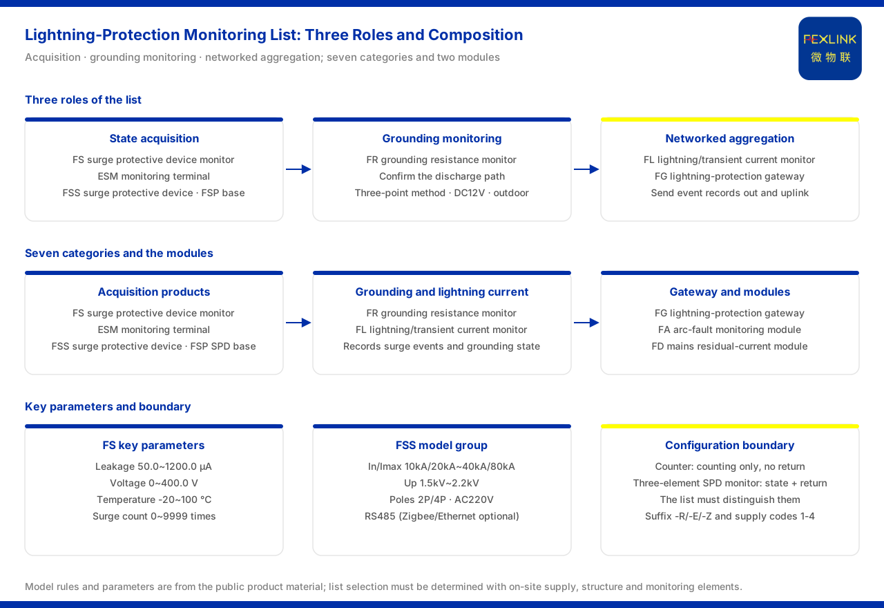
Direct answer
A complete lightning-protection monitoring configuration list should cover three roles at the same time: state acquisition, grounding monitoring, and networked aggregation. The product material lists intelligent lightning protection as an independent product line with seven product categories: the FS surge protective device monitor (lightning-protection monitoring module, for example FS-00011-R), the ESM intelligent lightning-protection monitoring terminal (SPD monitor, for example ESM-11312-R), the FSS intelligent surge protective device, the FSP SPD lightning-protection base (for example FSP-21000-R), the FR grounding resistance monitor (for example FR-01311-R), the FL lightning current / transient current monitor (for example FL-01222) and the FG lightning-protection smart gateway; separately it also lists the FA arc-fault monitoring module and the FD mains residual-current monitoring module. Whether a list is complete can be tested with three questions: is there an acquisition point, is grounding confirmed, and is the data sent out. The three questions map onto the three roles, because a monitoring scheme fails if any one of them is missing: without an acquisition point there is nothing to observe, without confirmation of grounding the state of the discharge path remains unknown, and without aggregation and uplink the readings never reach a platform where they can be used.
1. Acquisition class: first solve how SPD state is obtained
The first thing a list must make clear is what is being acquired. The FS surge protective device monitor takes the module form, and its model rule encodes the voltage channels, leakage-current channels, temperature channels, digital inputs and grounding / surge elements into the field positions; its monitoring elements cover remote signalling, switch status, grounding status, surge count, leakage current, temperature, voltage and lifespan estimation. The example model FS-00011-R is DC12V supplied, and its key parameters include leakage current 50.0~1200.0μA, voltage 0~400.0V, temperature -20~100℃, surge count 0~9999 times (minimum trigger 0.1kA) and lifespan estimation 0~100%.
When a terminal-level complete presentation is needed, the ESM intelligent lightning-protection monitoring terminal (SPD monitor) is the reference. It combines the model from supply, display, phase count, current parameter and version, where the version is divided into a basic four-element version and a flagship multi-element version; its monitoring elements include switch status, grounding status, surge count, leakage current, temperature, voltage, humidity and lifespan estimation. It should be noted that for some models the display annotation differs between the selection material and the model rule, and the actual order version governs.
Below these come two products that combine the device body with access. The FSS intelligent surge protective device joins the surge-protection body with monitoring: its model group covers In/Imax from 10kA/20kA up to 40kA/80kA, Up from 1.5kV to 2.2kV, and 2P / 4P pole counts, with AC220V supply across the series, RS485 communication, and Zigbee or Ethernet selectable by suffix. The FSP SPD lightning-protection base (for example FSP-21000-R) works with an existing surge protective device in base form and takes the access role; the two models in its model table differ only in whether temperature monitoring is included.
2. Grounding class: confirm the discharge path of lightning protection
Beyond acquiring the SPD state, the list must also answer whether grounding is reliable. The model rule of the FR grounding resistance monitor (for example FR-01311-R) encodes signal acquisition, detection principle, installation method and supply into field positions, with the detection principle divided into the loop method and the three-point method and the installation method into outdoor and indoor. The models FR-01311-R/Z/E all use the three-point method, DC12V and outdoor installation, and differ only in communication, corresponding to RS485, Zigbee and Ethernet respectively.
3. Lightning current and networking: send events out
The FL lightning current / transient current monitor carries lightning-event recording, and its model rule encodes the detection range, channel count, function, installation method and supply into field positions: the detection range is divided into two tiers, 1kA~120kA and 0.1kA~1kA, and the function into peak, peak plus energy, waveform and waveform plus energy. Data aggregation and uplink are carried by the FG lightning-protection smart gateway, which forms the networking role in the list.
4. Do not confuse a counter with a monitor
There is one easily mistaken boundary: an ordinary lightning-protection counter that counts only and has no communication return capability, and a three-element SPD monitor that has both state monitoring and communication return capability, are two different configurations. A lightning-protection monitoring configuration list must distinguish the two; otherwise a list may seem to enumerate products while in practice no state data that can be returned is obtained. The two are not interchangeable by virtue of both being "lightning-protection" products: one answers only how many events accumulated locally, the other answers what the state of the device is and can carry that state back over a communication channel.
5. Suffixes and supply are the language of the list
The communication and supply of all products in the list follow one common convention: the suffix -R is RS485 (Modbus), -E is Ethernet (MQTT) and -Z is Zigbee (Modbus), with 4G (MQTT) optional for some products; and for lightning-protection products the supply codes 1 to 4 correspond to DC12V, AC220V, solar and lithium battery respectively. This set of codes is the language that helps check product categories; whether a given power source is available on site should still be subject to the actual supply conditions. Reading the suffix tells the reader how a product is intended to be networked, and reading the supply code tells the reader what power the site must provide, so the two together keep a list consistent with the field rather than merely with a catalogue.
Applicability and limits
First, this article explains only the categories that a lightning-protection monitoring configuration list should cover; its factual boundary is limited to what the product material lists, and it introduces no standard clause, parameter, certification or case that is not listed.
Second, the seven-category composition of the product line and each product's model rule and parameters (including leakage current, voltage, temperature and surge count) are all existing records of the material; this article does not infer the specifications of unlisted models on that basis, nor does it make any performance or result inference.
Third, the distinction between an ordinary lightning-protection counter and a three-element SPD monitor, as well as the suffix and supply codes, is limited to the wording of the material; this article does not extend it into a general conclusion about field configuration.
Fourth, the specific model selection for a list must be determined in conjunction with on-site supply, structure and monitoring elements; this article provides no selection-calculation result.