 FEXLINK Research Institute
Direct Answer
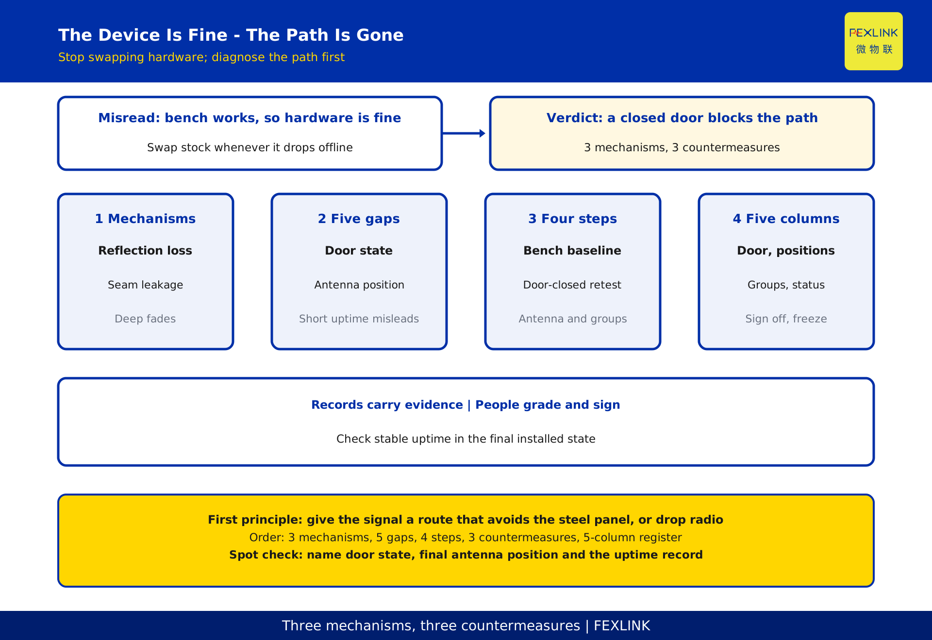
A sensor that works outside a cabinet and vanishes once installed is rarely faulty - the metal enclosure has cut the radio path. The cabinet acts like a closed metal cavity: the surface reflects the wave, internal reflections build deep fades, and only door seams, viewports and cable entries leak energy out. Three countermeasures follow: move the gateway antenna outside the cabinet or raise it, group cabinets instead of covering the whole room from one point, and give critical points a wired backup. Turning up transmit power is not one of them. This is a mechanism note, not a safety work procedure: openings, antenna routing, ingress protection and fire sealing are decided by qualified personnel under the permit and design documents. No operating steps, frequency or power figures, conformity ruling or performance guarantee.
1. Rule Out a Broken Device First: This Is a Path Problem
The common mistake is swapping hardware: a point appears outside the cabinet, drops off inside, and another batch is ordered. Yet only one condition changed - a metal enclosure now sits between node and gateway. Hold the variables steady and the conclusion flips: the device is the same, the path is different.
A reproducible test is the door check: offline with the door shut, back online when it opens to a certain angle - evidence that energy enters through seams and the problem is obstruction, not hardware. If it stays offline with the door open, the investigation turns to supply, addressing, configuration and the gateway side: the layered commissioning of wired buses, covered separately. This article treats only the "door shuts, signal goes" case, and the door check is a qualitative discriminator, not an operating step or safety permit.
2. Why a Metal Cabinet Behaves Like a Shielded Cavity: Three Mechanisms
Strictly, a cabinet is not an ideal shield: door seams, viewports, vents and cable entries are discontinuities. But for a node inside and a gateway outside, the link sees a cavity with very high attenuation.
| Mechanism | What happens physically | Cabinet feature | Observable symptom |
|---|---|---|---|
| Reflection and eddy-current loss | The metal surface mostly reflects the incident wave; induced currents add loss, so little energy enters | Steel panels, door, side plates | Drops when the door shuts, returns when it opens |
| Seam leakage and coupling | Energy leaves mainly through gaps and openings; their size and shape govern how much | Door seams, viewports, cable entries, vents | Different positions in one cabinet behave differently |
| Internal multipath and deep fades | Repeated reflections form standing waves; signal cancels at some positions | Mounting point, near busbars and partitions | Moving a point slightly changes its status |
The cabinet does not make the signal "a bit weaker": it consumes a large part of the link budget, and the result is strongly position-dependent. Trial-and-error repositioning cannot be replicated or handed over; only a structural response belongs in a design. This is a qualitative layer - no attenuation figures, limits or distance values, and actual coverage follows the site survey and signed records.
3. Where Bench Tests Diverge From Installed Operation: Five Differences
A bench test is free space with little obstruction; installed operation is a metal cavity, dense metalwork and a shut door. Five differences mean a clean bench record cannot serve as acceptance evidence.
| Difference | Bench test | Installed operation | Why it changes the verdict |
|---|---|---|---|
| Propagation path | Mostly line of sight | Must pass a panel or squeeze through seams | Different order of attenuation |
| Boundary state | Cabinet open | Door shut and kept shut | Open-door data cannot be extrapolated |
| Surroundings | Open, little interference | Busbars, partitions, adjacent cabinets | Multipath adds to obstruction |
| Antenna position | Hand-held, temporary | Fixed, close to metalwork | Position-sensitive; a few centimetres matter |
| Judgement | One frame arrives | Long-term availability and packet loss | A moment of uptime is not stable operation |
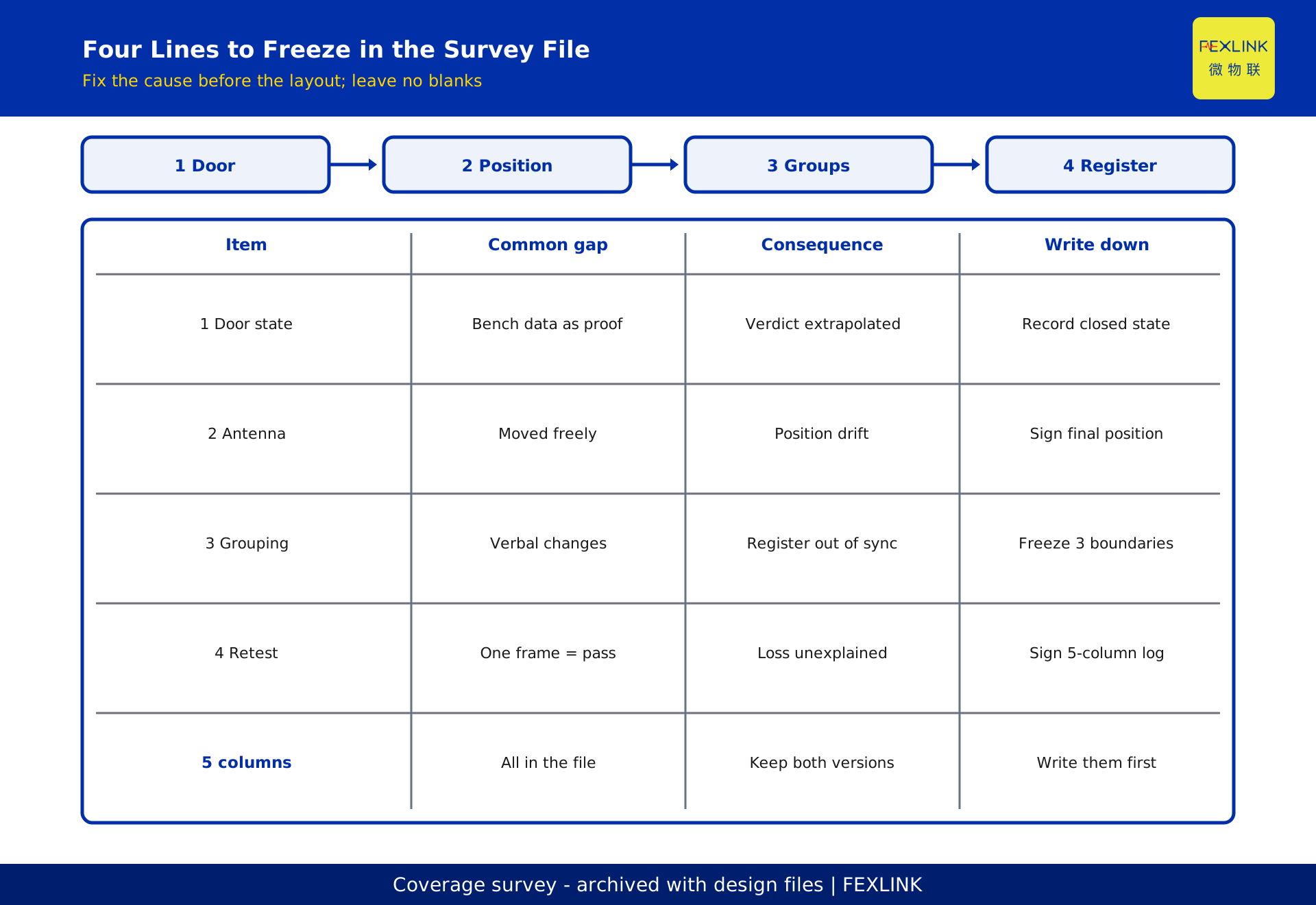
Survey records must state door state, node position, final antenna position, gateway position and neighbouring cabinet states; omit one and the same dataset supports two conclusions. A bench test confirms only that the device works, not that it works installed. Usability follows the availability record under the agreed observation window.
4. A Four-Step Localisation Sequence
The order is fixed, steps are not skipped, and no conclusion rests on one observation. Each step leaves a record naming its input, observation and outcome.
| Step | Input | What to observe | Where the result goes |
|---|---|---|---|
| 1 Bench baseline | List of nodes to install | Supply, join, reading | Proceed only if healthy; otherwise device and configuration checks |
| 2 Door-closed retest | The same node after installation | Change in status before and after closing | A clear difference means obstruction; record door state |
| 3 Antenna position | Antenna routing and raising plan | Status change at each point | Fix final antenna position and group boundaries |
| 4 Network convergence | Cabinet groups and critical-point list | Long-term availability, loss distribution | Produce and jointly sign the coverage register |
The step 2 door check is a qualitative discriminator under permit and safe conditions. Steps 3 and 4 involve openings, feeder routing and repositioning by qualified personnel against the design documents; no operating method is given. If the four steps still fall short, do not swap hardware - return to the path: a missed obstructing face, an unreasonable group, a critical point that should be wired.
5. Countermeasure One: Move the Gateway Antenna Outside and Raise It
The most effective action is to get the antenna out of the cavity. Left inside, both transmit and receive ends sit in a box; routed outside and raised above the cabinet row, the link no longer crosses a full steel panel. Feeder loss, connector protection, ingress protection, fire sealing, earthing and routing effects all offset part of the gain and need closing out against the design documents. "The antenna is outside now" is not a pass criterion.
The test is whether that point stays reliably online in its final installed state, not how high the antenna is drawn. Every point needs a final-position record and its availability record, and a position change requires re-sign-off. Because position is sensitive, antenna routing is a one-time design decision, not a site-adjustable freedom.
6. Countermeasure Two: Group Cabinets Instead of Covering Them All at Once
One gateway fighting an entire row lets the worst path decide the whole system. Dividing the row into groups by cabinet line, obstruction and point distribution, with a receiving point each, leaves every node facing a controlled path within its group and is more reproducible than centralised coverage. Groups follow whether obstructing faces are continuous and paths are alike, not even cabinet-number cuts; boundaries go into the coverage register against the point list.
Each group keeps its own availability and loss record, so an anomaly is localised rather than guessed across the room; first checks are that group's antenna position and door states. Cross-group moves need fresh confirmation, otherwise the register stops matching reality.
7. Countermeasure Three: Wired Backup for Critical Points
However well the wireless layout is tuned, some points are too awkward or too consequential for radio alone. Wired acquisition alongside the wireless groups gives the link a deterministic route; it is not an admission of failure. Grading is confirmed by owner and designer on importance, consequence and maintainability, not picked by the installer for convenience.
| Dimension | Question | Typical case for wired backup |
|---|---|---|
| Consequence | Would a missed reading affect a safety judgement | Critical hot spots where failure is unacceptable |
| Position | Is it on the worst obstructing face | Deep inside a cabinet, behind several partitions |
| Maintainability | Can it be re-tested during a later outage | Long-term no access, no antenna adjustment |
| Evidence | Is a continuous record required | Points needing a continuous curve as operating evidence |
Wired and wireless points are marked on the same list so the ledgers cannot diverge. No interface form, cable specification or model parameter is given; selection follows the design documents.
8. De-identified Worked Example: 24 Cabinets / 48 Points
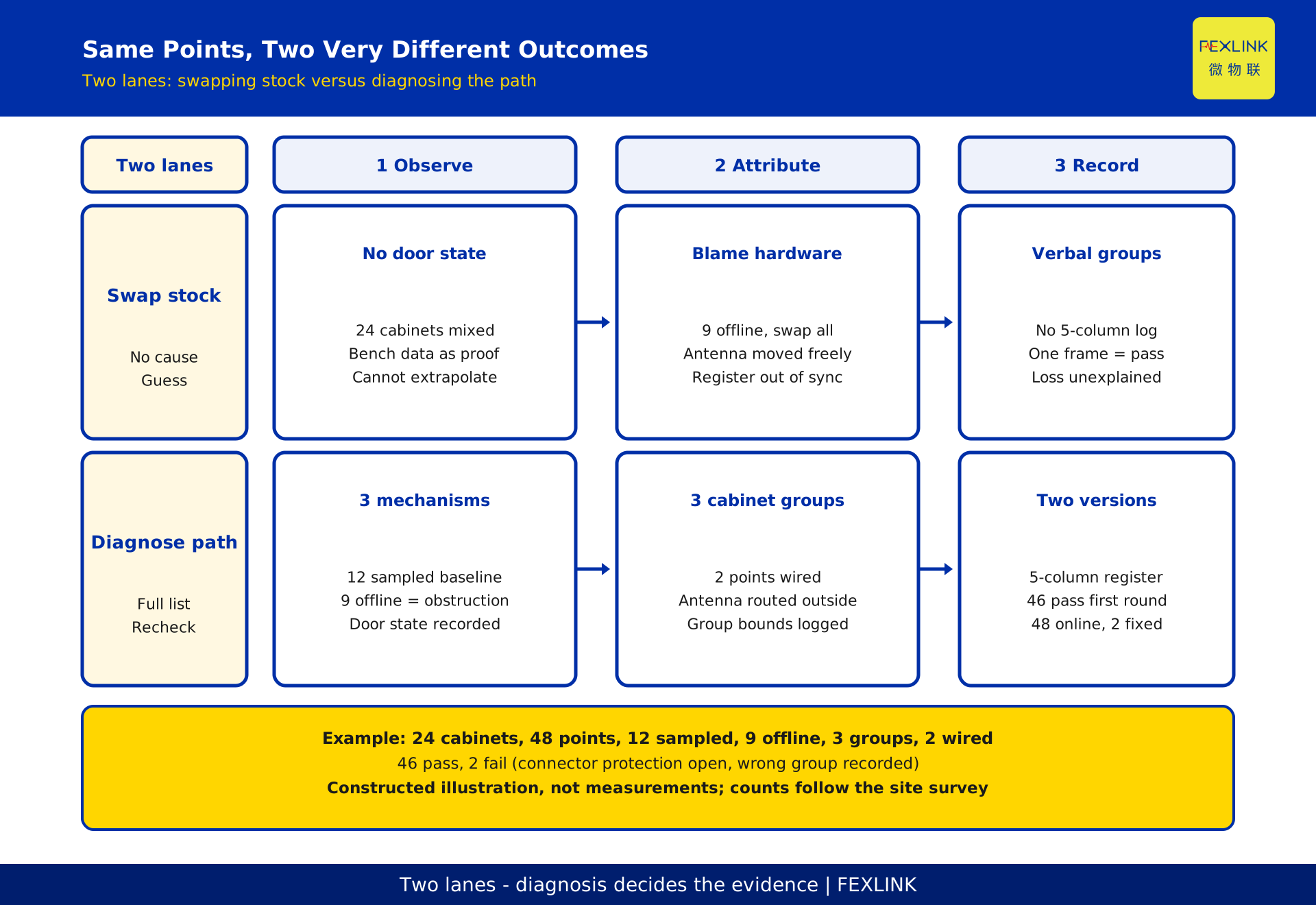
The following is a constructed, de-identified illustration - not a real project, not measured values, not a recommended configuration. Suppose a distribution room has 24 metal cabinets and 48 temperature points. A bench sample of 12 points is fully online; with the cabinets closed, 9 of them are offline, and all return when the doors are opened. Following section 2, the cause is obstruction, so the row is divided into 3 groups, each group's antenna is routed outside, and 2 critical points are switched to wired backup.
| Stage | Action | Points online | Deliverable |
|---|---|---|---|
| Baseline | Sample 12 points outside cabinets | 12 online | Bench baseline record |
| Installed | Retest with doors shut | 9 offline | Door-state difference record |
| Treatment | 3 groups, 2 points wired | 46 pass first round | Group and point list |
| Convergence | Retest after 2 fixes | 48 online | 5-column coverage register |
The 2 first-round failures were an unclosed connector-protection item and a wrong group assignment - records and execution, not mechanism. The example illustrates sequence and evidence only; it promises no coverage, availability or equipment count. Real numbers follow the site survey, design documents and contract.
9. Why Turning Up Transmit Power Is Not the Answer
Raising transmit power is the first idea on site and the easiest to get wrong. First, transmit parameters are bounded by product ratings and radio regulations; no power figures or adjustment methods are given. Second, the link is two-way: boosting the node still leaves the downlink unheard, and multipath and deep fades do not vanish. Third, higher power eats into the receive dynamic range of other nodes and can turn a local problem into a group-wide one. Fourth, obstruction is structural; masking it treats "online for now" as "stable over time", and the fault returns when door states change.
Turning up power is a prohibited action, along with substituting open-door data for closed-door records, leaving antenna position adjustable without re-sign-off, keeping group boundaries verbal, using a moment of uptime instead of a long-term record, and blaming every dropout on hardware while swapping stock.
10. Solution-Side Roles and Responsibilities
The related solution is busbar monitoring (FEXLINK-BMS) with an edge aggregation layer, described only as a qualitative split: wireless nodes on the acquisition side, gateways and platform on aggregation, display and recording. The split shows which link segment the obstruction occurs on. No model parameters, capability claims, inferred field performance, procurement commitment, or substitute for the contract, design documents or qualified opinion. Registry models are registered only; none are cited.
Responsibility splits three ways: installer and integrator submit survey records, grouping plan and point list and execute them; owner and designer confirm critical-point grading, observation window and criteria; supervisor or independent reviewer checks door states, final antenna positions, coverage register and sign-offs. Planning and passing the same work yourself produces a conclusion nobody can re-check.
Frequently Asked Questions (FAQ)
Q: If it works with the door slightly open, doesn't that prove the device is fine?
Quite the opposite - it proves the path is the problem. One node changing status with only the door state changed is qualitative evidence of obstruction. It does not prove stable operation with the door shut, so a record in the final installed state is still required, and the check needs a permit.
Q: Can we just raise transmit power and push the signal out?
No, and it should not be a design action. Transmit parameters are bounded by product ratings and radio regulations; the link is two-way and internal multipath does not disappear with more power. Obstruction is structural. No power figures or methods are given.
Q: Routing the antenna outside means an opening - will that affect cabinet protection?
It may affect ingress protection, fire sealing, earthing and internal layout; qualified personnel must close out each item against the permit, safety rules and design documents. No opening dimensions or operating steps are given, and no conformity ruling is made.
Q: Wouldn't wiring every point be simpler?
Wired backup is graded by importance, consequence and maintainability and covers only confirmed critical points. Wiring everything changes construction scope, outage needs and cost - a different design, outside this article. The owner and designer set the grading.
Q: After following this sequence, can you guarantee no more packet loss?
No. This article offers mechanism and sequence, not a coverage or availability guarantee. Real results depend on cabinet construction, door state, antenna position, interference and operating mode; the verdict follows the signed survey and observation-window records.
Scope and Limitations
This applies to brownfield wireless temperature monitoring in rooms with dense metal cabinets, a defined point list, agreeable group boundaries and an independent reviewer; not to unobstructed new builds, sites without a work-permit process, or acceptance substituting one moment of uptime for staged records. The registry lists no standards, so there are no standard or clause numbers, conformity tables or validity assertions. No frequency, power, attenuation, distance or opening dimensions; no steps for cabinet openings, antenna routing or feeder installation; no safety ruling. The 24 cabinets, 48 points, 12 sampled, 9 offline, 3 groups, 2 critical points, 46 passes and 2 first-round failures, and the 5-column coverage register in section 8 are constructed, de-identified illustrations - not measurements, not a recommended configuration. Solution and product names are qualitative layers with no procurement commitment. Wired-bus commissioning is a separate article.
Frequently Asked Questions
Why Does a LoRa Sensor Vanish the Moment It Goes Inside a Metal Cabinet?
A sensor that works outside a cabinet and vanishes once installed is rarely faulty - the metal enclosure has cut the radio path. The cabinet acts like a closed metal cavity: the surface reflects the wave, internal reflections build deep fades, and only door seams, viewports and cable entries leak energy out