 FEXLINK Research Institute
Direct Answer
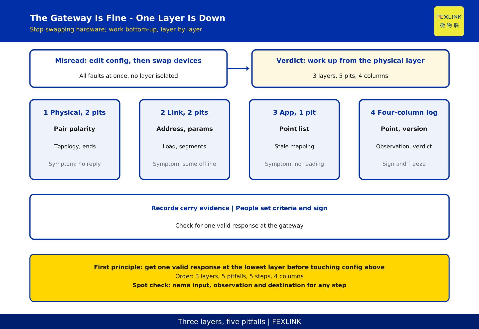
A gateway powers up, yet no device appears on the back end. Usually the gateway is fine; one of three layers - physical, link, or application - has not come up. Commissioning time goes to guessing, not fixing: change the configuration, swap devices, then find the differential pair reversed. Work bottom-up, change one variable per layer, record each observation, and rest every upper-layer conclusion on a confirmed lower layer. This piece covers the 5 common site pitfalls, a 5-step decision tree and a 4-column commissioning register a third party can re-run. It is a troubleshooting method note, not a compliance document: no protocol numbers, years, clause numbers, baud rates, parity, termination resistance, address ranges, device-count or cable-length limits, and no conformity verdict. Manuals, design documents and the contract remain authoritative.
1. Do Not Touch the Configuration First: "Nothing Connects" Is a Layer Problem
"Nothing connects" and "one device does not connect" are different problems: the first points at shared elements (bus wiring, device power, gateway serial-port parameters, point-list release), the second at a single device's address or wiring. Fix the test first: "up" means the gateway sees one valid response, not that a card appears on the platform page. A blank page may only mean modelling and mapping are unfinished, which sits in the application layer.
The boundary is simple: the physical layer checks signals on the wire, the link layer matches request and reply, the application layer places each returned value. All three share one bus, so any failure looks identical from above: no data. Skipping steps means rewriting upper-layer configuration while the link was never established.
2. Two Physical-Layer Pitfalls: Polarity and Termination
Pitfall 1 is reversed or crossed differential wiring. The bus still carries power, but neither end decodes a frame; the gateway transmits, gets no response or sees garbage. Check the pair against design documents and terminal markings segment by segment, confirming both ends share the designation - not by wire colour, which changes across cabinets and terminal blocks.
Pitfall 2 is topology and termination. Mixing daisy-chain with star branches, long spurs, or termination at mid-span or twice at the ends lets reflections break frame boundaries. Check topology and branches against the design document and confirm termination appears only at the two ends. Resistance values, spur lengths and segment boundaries come from the manual and design documents; no values here.
Both share one signature: replacing any device changes nothing, because the fault lies outside the devices. Swapping hardware yields no information here.
3. Two Link-Layer Pitfalls: Parameter Consistency and Bus Load
Pitfall 3 is a mismatched station address or serial-port parameter. Two devices sharing an address collide; a gateway whose rate, parity or stop-bit setting differs gets no response from the whole segment. Compare the point list, address table and actual configuration item by item, change one thing at a time, retest. Values come from design documents and manuals; no rates, parity or address ranges here.
Pitfall 4 is bus load and segmentation. Too many devices, excessive cable length, or mixed rates in one segment produce the classic "each device tests fine alone, packets drop once all are connected". Segment by circuit or cabinet row, connect one group at a time and watch whether loss grows with the count. Device-count limits, cable lengths and segment counts come from the manual and design documents; no limits here.
They also compound: parameter mismatch looks like "some devices offline", overload like "intermittent". Attributing the latter to interference hides the segmentation problem.
4. One Application-Layer Pitfall: Point List and Register Mapping
Pitfall 5 is a working link with missing or shifted platform readings. Responses exist on the bus, so the fault is in the point list: register addresses, data types, byte order, scaling factors, point names and gateway acquisition items disagree, or the model references an older release. First confirm the gateway can read a raw value. If it can, the issue is mapping or modelling, with no need to return to the physical layer; then check point-list version, point ID, data type and unit.
This is easily misread as "the device never connected" because the page looks equally empty. Check the gateway log for a valid response: a response keeps you in the application layer, none sends you back to the first two. Mixing them is the main source of rework.
5. A Five-Pitfall Decision Tree: Bottom-Up, No Skipping
The order is fixed. Each step handles only its own layer; a failure must not be answered by changing configuration above it.
| Step | Check | Pass criterion | If it fails |
|---|---|---|---|
| 1 Static check | Terminals, polarity, topology, termination | Matches design; no reversals or duplicate termination | Return to physical layer |
| 2 Single-device baseline | One device close-linked to the gateway | One valid response read | Return to physical layer / check device and power |
| 3 Incremental connection | Add devices per the point list | Retest after each addition; loss does not grow with count | Return to link layer for addresses and segmentation |
| 4 Parameters and point list | Addresses, parameters, point-list version | All three agree and raw values readable | Return to link / application layer for mapping |
| 5 Modelling and observation | Point names, units, observation-window log | Stable over time and readings re-checkable | Sign and freeze the 4-column register |
Each step records three things: input (lists and versions), observation (response, raw value, loss record) and destination (pass, or which layer to return to). Any step can then be repeated by a third party.
6. What Each Step Records: A Four-Column Commissioning Register
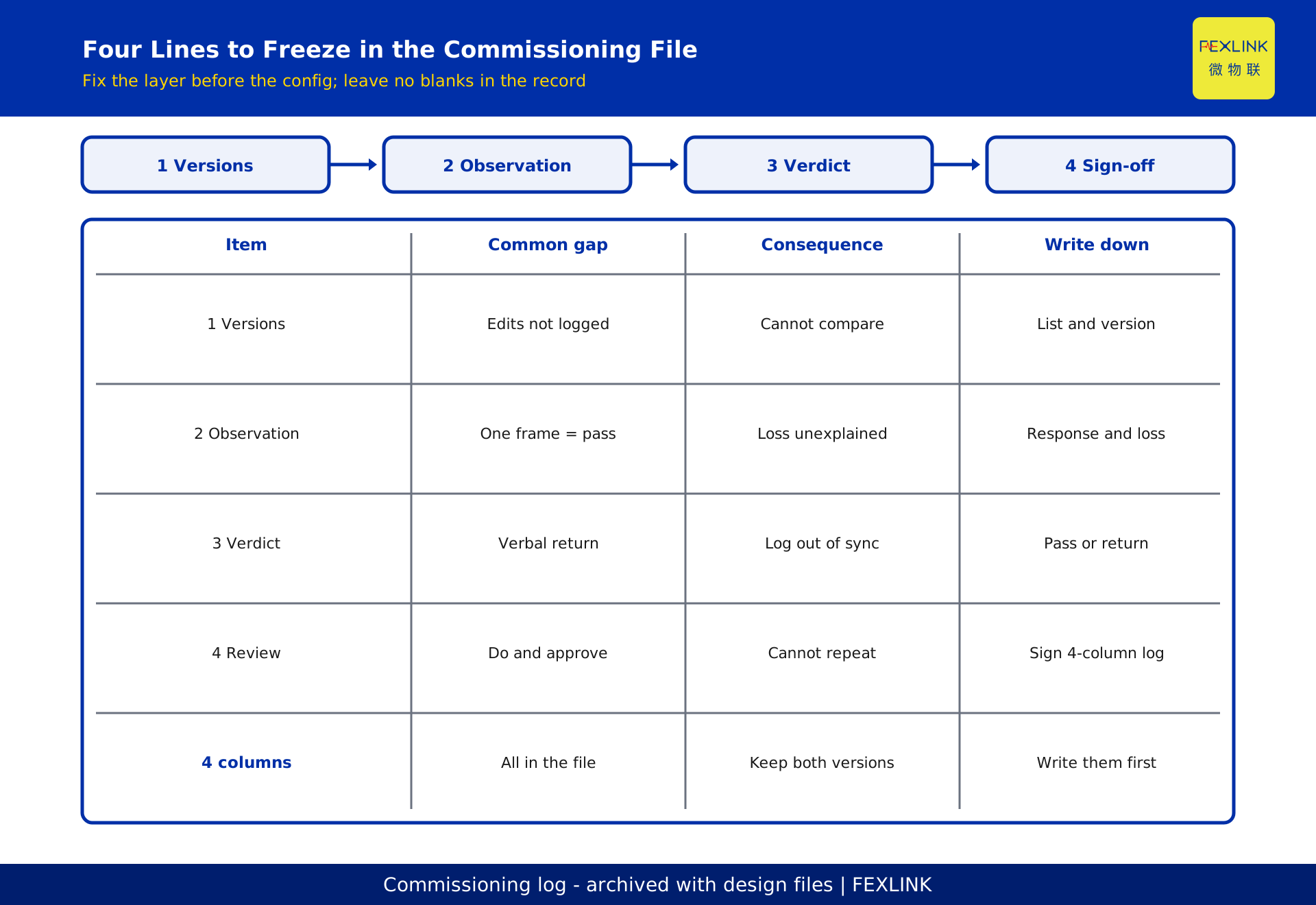
Compress the record into 4 columns as the single reconciliation register: point ID and circuit; step input (list, parameter and point-list versions); observation (response, raw value, loss record); conclusion and destination (pass or return layer, signer, time). Keep both versions, never overwrite.
| Column | What it holds | Why it is required |
|---|---|---|
| 1 Point ownership | Point ID, cabinet, segment | Otherwise "which device is offline" cannot be answered |
| 2 Input versions | Point list / parameters / point list release | Otherwise a swap changes the variables and comparison is lost |
| 3 Observation | Response present, raw value, loss record | Separates "not connected" from "connected but not displayed" |
| 4 Conclusion | Pass or return layer, signer, time | Lets a third party repeat the work |
The register's value is making one set of symptoms admit only one explanation. Drop a column and wiring faults, address collisions and point-list offsets all collapse into "the device is unstable".
7. De-identified Example: Bringing Up 24 Terminals
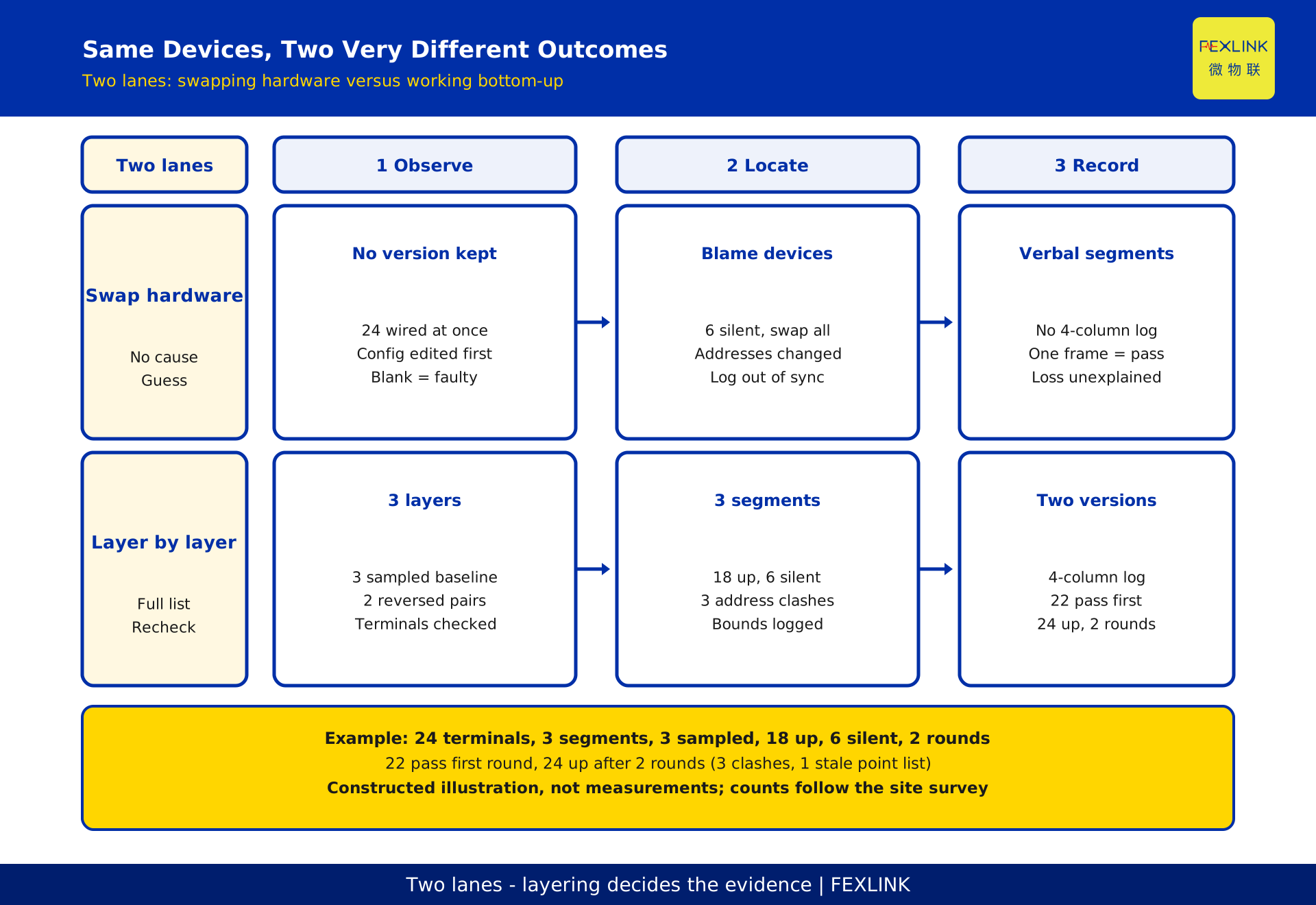
The following is a constructed, de-identified walkthrough - not a real project, not measurements, not a recommended configuration. Assume 24 terminals across 3 bus segments, and a platform showing nothing after the gateway is racked. Following Section 5:
Step 1 static checks find 2 reversed differential pairs and 1 spur not run as daisy-chain; once corrected, baseline conditions exist. Step 2 close-links one device and samples 3, all returning valid responses, so gateway parameters are usable. Step 3 adds devices one at a time; at 18 connected, 6 give no response - 3 duplicate addresses, 3 with parameters inconsistent with their segment. Step 4 finds 1 reference to an older mapping release. Step 5, after 2 rounds of fixes, brings all 24 online with complete observation records, and the 4-column register is signed and frozen.
| Stage | Action | Devices online | Deliverable |
|---|---|---|---|
| Static check | Polarity, topology, termination | 0 | Design-document comparison record |
| Single baseline | 3 devices close-linked | 3 | Valid-response record |
| Incremental | Connected up to 18 | 18 | Segmentation and connection-order record |
| Attribution and fix | Resolve 6 silent devices and 1 stale point list | 22 | Two-version change record |
| Observation | Retest after 2 rounds | 24 | Signed 4-column register |
The example shows only the order and evidence structure. Real counts and parameter values come from the site survey, manuals and design documents; it promises no uptime or configuration quantities.
8. Why Swapping Gateways or Devices Rarely Helps
Only pitfall 5 relates directly to gateway configuration, and only after the link is up. The first four live in wiring, devices or parameters; a new gateway changes none. Worse, a swap erases evidence: wiring redone, addresses reset, point lists re-imported. By the second reproduction the variables have changed and the registers cannot be compared.
Before any swap, fix three things: photograph terminals and wire numbers, export parameters and the point-list version, and write in the 4-column register which layer is suspect and what the swap should verify. Treat the swap as one recorded variable change, never a conclusion. If it still fails, return to that layer and reapply the criterion instead of replacing the next item.
9. Common Misreads and Four Prohibited Actions
Five common misreads: reading a blank platform card as proof devices never connected; judging polarity by wire colour instead of terminal markings; declaring a segment healthy after one device; changing parameters without a reset and fresh sign-off; blaming every intermittent fault on interference.
Four prohibitions belong in the commissioning file: (1) bulk-editing gateway parameters before a static check; (2) changing addresses or parameters without versions or a before-and-after pair; (3) substituting a momentary online state for a long observation-window record; (4) both implementing and approving the work with no independent review. Do not reconnect anything unrelated to commissioning on energised circuits. Work involving live parts, current-transformer secondary circuits or primary conductors must be assessed by qualified personnel against the work permit, safety rules and design documents. No operating steps or safety determinations are given here.
10. Solution-Side Roles and Responsibilities
The associated device-edge-cloud architecture is a qualitative split only: terminals are acquisition, the gateway edge aggregation and protocol adaptation, the platform modelling, display and recording. It indicates which layer failed; it writes no model numbers or parameters, evaluates no capability, infers no measured performance and makes no procurement commitment. Registry models are recorded there only, not cited here.
Responsibility splits three ways: the contractor and integrator submit the point list, address table and point-list version and run the layered checks; the owner and designer confirm segment boundaries, parameter conventions and acceptance criteria; an independent reviewer checks the 4-column register, raw response records and sign-offs. Implementing and approving the same work makes the conclusion unauditable.
Frequently Asked Questions (FAQ)
Q: The gateway indicators look normal but the platform shows nothing - is the gateway faulty?
Indicators only show power, not that a link exists. Check the gateway log for a valid response: none means start at Step 1 of Section 5 through the physical and link layers; a response means a point-list or modelling problem. Swapping the gateway changes none of the first four pitfalls and erases the evidence.
Q: Can we connect every device first and tune parameters afterwards?
Not advisable. With everything connected, wiring, address collisions, load and point-list faults appear at once as "no data", so nothing can be assigned to a layer. Adding devices one at a time with a retest after each is what makes "which device started the decline" recomputable evidence.
Q: What exactly should the station addresses and baud rate be?
No values here. Parameters follow design documents, device manuals and the agreed address table; they must be consistent within a segment and addresses must not repeat. Change one item at a time, retest, and record the version in the 4-column register. Guessing piles a parameter mismatch onto any wiring fault.
Q: Where does termination go, and how many?
Check topology and branches against the design document and confirm termination appears only at the two ends, never duplicated. Resistance values, spur lengths and segment boundaries come from the manual and design documents. No values or installation steps here; work near live parts is assessed by qualified personnel under a work permit.
Q: Will following this tree guarantee no further packet loss?
No. This is a layered troubleshooting order and an evidence structure, not an uptime or communication-quality commitment. Real results depend on cabinet construction, cable routing, interference and operating conditions; the verdict rests on the jointly signed observation record. Adding devices or changing segments later means revisiting that layer and updating the register.
Scope and Limitations
Applies to wired serial-bus commissioning in existing distribution rooms with a defined, versioned point list and segment-by-segment connection. Not for wireless links blocked by metal cabinets (a separate article), sites without design documents or a work-permit process, or acceptance based on a momentary online state instead of an observation-window record. The standards listed in the registry resolve, on name-checking, to a protocol-family abbreviation and a transmission mode of an open serial-link protocol; they are background in the metadata only. The text carries no standard numbers, years, clause numbers, conformity tables or "currently valid" claims, and gives no rate, parity, termination resistance, address range, device-count or cable-length limit, no live-work steps and no safety determination. Section 7 figures - 24 terminals, 3 segments, 3 sampled, 18, 6 silent, 1 stale point list, 2 fix rounds and 4 register columns - are de-identified constructions, not measurements or recommended configurations. Solution and product names are qualitative labels only, with no procurement commitment.
Frequently Asked Questions
Gateway Is Up but Not a Single Device Connects
A gateway powers up, yet no device appears on the back end