 微物联研究院
Direct Answer
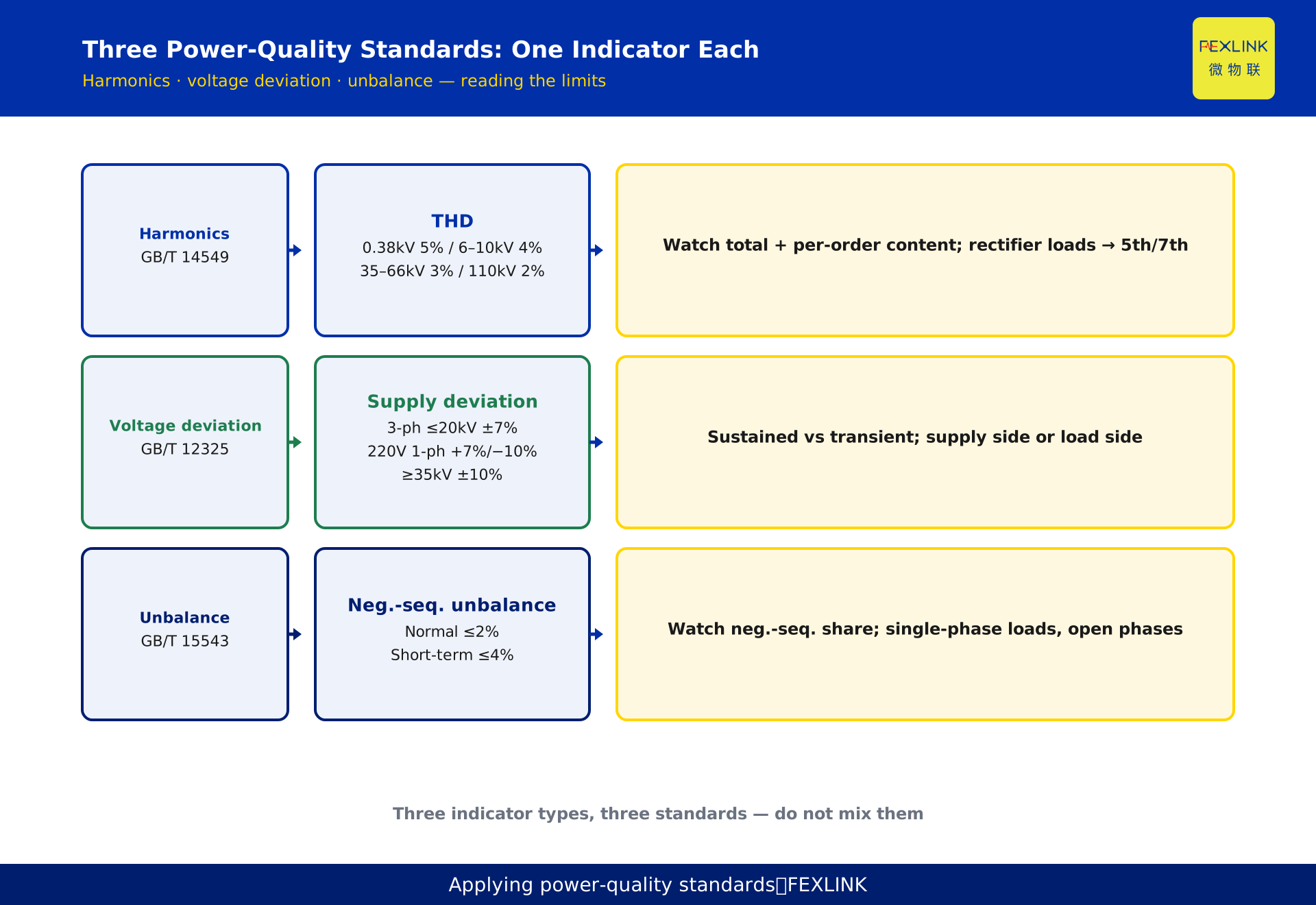
Power-quality monitoring rests on three core national standards: harmonics follow GB/T 14549 "Power Quality — Harmonics in Public Supply Networks"; voltage deviation follows GB/T 12325 "Power Quality — Supply Voltage Deviation"; three-phase voltage unbalance follows GB/T 15543 "Power Quality — Three-Phase Voltage Unbalance". Monitoring products should set over-limit judgment and alarm thresholds against these three standards as the compliance baseline for power quality. A quick way to remember: harmonics look at distortion ratio, voltage looks at deviation percentage, unbalance looks at the negative-sequence component — each standard governs one type of indicator, so do not mix them.
What the Three Standards Each Govern: Do Not Mix Three Indicator Types
Power quality is "a set of indicators," not "one indicator." Voltage, current, and frequency each have their own quality dimensions, and the three most relevant to everyday monitoring are harmonics, voltage deviation, and three-phase unbalance. A common mistake is to lump all three together and vaguely "watch power quality," which corrupts alarm attribution — a harmonic over-limit gets measured against the voltage-deviation standard.
The division of labor is clear:
- GB/T 14549 governs harmonics: whether harmonic content in voltage and current exceeds limits;
- GB/T 12325 governs voltage deviation: whether the deviation of the actual supply voltage from the nominal value stays within the allowed band;
- GB/T 15543 governs three-phase unbalance: whether the asymmetry of three-phase voltage/current exceeds limits.
Once the division is understood, reading each standard becomes straightforward.
There is also a shared logic worth noting: all three standards measure "degree of deviation," not "presence or absence." Harmonics always exist (no grid is perfectly clean), voltage always deviates, and three phases are never perfectly symmetric — the standards set not "zero deviation" but an "allowed deviation ceiling." Monitoring therefore does not ask "is there deviation" but "has deviation crossed the ceiling, by how much, for how long," which defines the alarm logic: normal small deviations do not alarm; only over-limit does.
Reading Harmonics: GB/T 14549
GB/T 14549 sets limits for harmonics in the voltage and current of public networks. Two quantities matter most in daily monitoring:
Total harmonic distortion (THD). It reflects the share of harmonics in total. Limits differ by voltage level: 5% for 0.38 kV networks, 4% for 6–10 kV, 3% for 35–66 kV, and 2% for 110 kV. The higher the voltage level, the stricter the allowed distortion.
Individual harmonic content. The standard separates odd and even harmonics with their own limits; odd-harmonic content is capped by order band (e.g., 3rd–5th, 7th–9th, 11th and above), and even harmonics are usually stricter. This reminds the site: look not only at the total but at which specific orders are over — certain orders often point to specific load types (e.g., rectifier equipment produces 5th and 7th harmonics).
Monitoring landing: harmonic alarms should present both THD and the main over-limit orders, so the pollution source direction is easy to judge.
Reading Voltage Deviation: GB/T 12325
GB/T 12325 sets the allowed deviation band of supply voltage relative to nominal value. Common reading:
- Three-phase supply at 20 kV and below: ±7%;
- 220 V single-phase supply: +7% to −10%;
- 35 kV and above: ±10%.
Two points matter when reading. First, direction: single-phase supply allows +7%/−10%, asymmetric — do not collapse it into one number. Second, an over-limit voltage deviation is not necessarily a supply-side problem; large load starts can cause transient voltage dips on the load side, so attribution needs waveform and time-of-day context.
Monitoring landing: voltage-deviation alarms should distinguish "sustained over-limit" from "transient over-limit"; sustained is the more serious signal.
Reading Three-Phase Unbalance: GB/T 15543
GB/T 15543 sets limits for three-phase voltage unbalance. Common reading:
- During normal grid operation, negative-sequence voltage unbalance must not exceed 2%, and short-term (no more than 1 minute) 4%;
- Current unbalance is held to stricter standards, because it directly drives equipment heating and loss.
The core of unbalance is the "negative-sequence component share." Concentrated single-phase loads, uneven three-phase load distribution, open phases, and poor contacts all cause unbalance. Note the interplay: unbalance often carries zero/negative-sequence current and may compound harmonic problems, so attribution should look at the whole picture.
Monitoring landing: unbalance alarms should give the unbalance value, the negative-sequence share, and each phase's voltage/current, so it is clear which phase drags the whole down.
How Monitoring Products Align with the Three Standards
Aligning with national standards is not just writing three thresholds into configuration; it must be implemented at the measurement-principle, calculation-method, and alarm-logic levels:
Measurement and calculation alignment. THD, deviation percentage, and unbalance must be computed per the standards' definitions — harmonic analysis with the specified window and spectrum, unbalance from the negative-sequence definition — never an "approximation."
Threshold and grading alignment. Over-limit judgment follows the standard limits, configured per voltage level — the same monitor on different voltage-level circuits should use different harmonic limits.
Presentation and attribution alignment. Alarm messages should distinguish indicator type and show excess magnitude and over-limit orders, instead of lumping harmonics, deviation, and unbalance into one "power-quality alarm."
In FEXLINK's ESE power-quality monitor and FSE power-quality measurement-and-control unit, all three indicators are computed and graded per the standards; on site you only need to verify threshold configuration against the circuit's voltage level.
A three-step checklist helps: first, confirm the circuit voltage level and look up its THD limit (5% at 0.38 kV, 4% at 6–10 kV); second, confirm the supply mode (three-phase or single-phase) and its deviation band (three-phase ±7%, single-phase +7%/−10%); third, decide whether the condition is short-term and whether unbalance is graded at 2% or 4%. Three steps give all thresholds a standard basis — no more "using the 6–10 kV harmonic limit on a 0.38 kV circuit."
After an Over-Limit: Responsibility and Remediation
An important procurement note before that: standards alignment is inspectable. Ask the vendor which standard and version each alarm threshold is derived from, and whether THD and unbalance are computed per the standard definitions rather than approximated. A vendor who answers with standard numbers and versions is far more likely to deliver defensible monitoring data than one who only says "power quality included."
The basic principle for responsibility after a power-quality over-limit is "whoever causes it, treats it":
- Harmonic over-limit: mostly produced by nonlinear loads (rectifiers, drives, arc-type equipment); remediation is adding filtering, adjusting start-up, optimizing load structure;
- Voltage-deviation over-limit: distinguish supply side from load side — supply-side issues need coordination with the utility (tap changer, reactive compensation), load-side issues start with equipment start/stop and reactive demand management;
- Unbalance over-limit: the core is load allocation — rebalance single-phase loads across phases, treat asymmetric equipment, add balancing devices when needed.
Monitoring's value: at the moment of an over-limit, the system says "which indicator, by how much, for how long," turning responsibility disputes into decisions based on data.
The Relationship Between the Three Standards and Routine Reports
Power-quality reports (daily/monthly/annual) relate to the standards as "continuous comparison, periodic assessment":
- Daily report: whether the three indicators crossed limits that day, when and for how long, for prompt handling;
- Monthly report: statistics of over-limit frequency and magnitude distribution, judging "occasional" versus "chronic";
- Annual report: evaluate compliance item by item against the standards, as the basis for remediation investment.
A qualified report is one where "every indicator has a standard basis and every over-limit has magnitude and duration records" — that is what gives the report compliance-evidence value.
The relation between reports and alarms must also be clear: alarms are "real-time triggers," reports are "periodic accumulation." Alarms remind the site to act now; reports organize scattered alarms into patterns — which indicator keeps crossing, which time windows concentrate, whether remediation improved things. Only when alarms and reports work together does standard comparison move beyond single-event handling into the full loop of discover, handle, re-measure, evaluate. Many enterprises only push to install filtering after the monthly report shows harmonic over-limit month after month — that is the decision value of periodic accumulation. A practical habit is to review the monthly report in the first week of the next month: check the three indicators for frequency and magnitude, mark which circuits repeat, and confirm whether last month's remediation actually reduced the over-limit count.
Implementation Notes: Versions and Field Conditions
All three standards emphasize the currently effective version: GB/T 14549-1993, GB/T 12325-2008, GB/T 15543-2008. Three points on the ground: first, verify version and limits before configuring thresholds; second, special scenarios (sensitive loads with stricter requirements) may use stricter internal control standards but never below the national ones; third, field measurement conditions affect readings — transformer accuracy, wiring, and measurement windows all affect harmonic and unbalance results, so calibration and re-measurement belong in the process.
Scope and Limitations
The mapping and limit summaries of the three standards (GB/T 14549-1993, GB/T 12325-2008, GB/T 15543-2008) are public-standard arrangements; limits follow the currently effective versions. The alignment capability of the monitoring products (ESE power-quality monitor, FSE power-quality measurement-and-control unit computing and grading per the standards) follows the FEXLINK product knowledge base. Example scenarios are anonymized illustrations and do not refer to any specific customer; project-level power-quality assessment and responsibility determination must be performed by qualified professionals based on field measurement data and governing codes.