 微物联研究院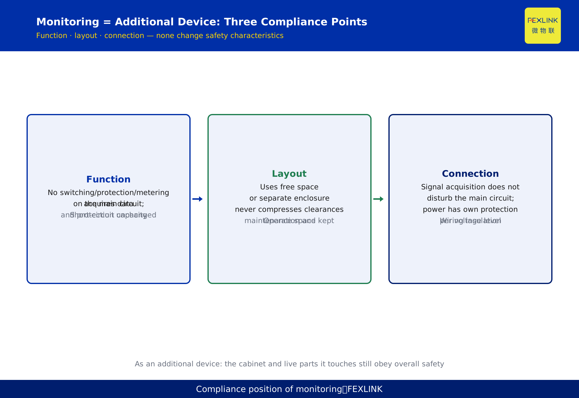
Direct Answer
Online monitoring products (monitoring terminals, current/temperature/residual-current sensors) installed inside low-voltage distribution cabinets do not need a second "distribution design," but they must stay coordinated with GB 50054-2011 "Code for Design of Low-Voltage Distribution": the installation position must not intrude on electrical clearances, enclosure protection must meet the site requirements, and the monitoring power supply must follow the protection coordination principle for distribution circuits. Understanding this code answers three practical questions — where the monitoring device may be installed, how it must be protected, and how its power should be taken. The core conclusion: a monitoring product is an "additional monitoring device" in the distribution system; it must not degrade the safety characteristics of the original distribution installation, and everything else aligns with the code's requirements for distribution equipment.
What GB 50054 Governs: Set the Boundary First
GB 50054-2011 "Code for Design of Low-Voltage Distribution" is the baseline code for low-voltage distribution design, applicable to low-voltage distribution design in new, expanded, and renovated projects at AC 1000 V and below, and DC 1500 V and below.
It governs not "a single device" but "how the distribution system is designed to be safe and reliable": arrangement and clearances of distribution equipment (cabinets, boxes, busbars, switching devices), configuration of protective devices (short-circuit protection, overload protection, residual-current protection), selection and routing of conductors, and the selection of enclosure protection degrees.
For online monitoring, the first value of understanding this code is setting the boundary: the code constrains the "distribution system design" layer; a monitoring product is a device installed inside that system, so its compliance question is not "whether it executes a distribution design code by itself" but "whether the distribution system remains compliant after it is installed." Phrased differently: introducing a monitoring device must not become a reason for the distribution system to become non-compliant.
The Position in the Code: Additional Device, Not Distribution Equipment
Distribution equipment has a defined scope and complete requirements in the code (enclosure structure, protection, clearances, protection coordination are all managed as distribution equipment). Online monitoring products do not belong to this category — they do not perform switching, protection, or metering on the main circuit; they measure voltage, current, temperature, residual current, and other electrical quantities and send the data out.
This positioning determines the compliance framework:
- Functionally, a monitoring device is additional monitoring equipment; it does not change the short-circuit capacity, protection configuration, or switching capability of the distribution installation;
- In layout, it occupies free space inside the cabinet or a separate enclosure, without compressing the mandatory clearances of the distribution equipment;
- In connection, its signal acquisition does not affect main-circuit operation, and its power supply has independent protection.
Positioning the monitoring product as an "additional device" rather than "distribution equipment" clarifies most compliance questions: the monitoring device does not need a full set of protection designed to distribution-equipment standards, but the cabinet it lives in, the live parts it touches, and the energy it consumes still obey the overall safety requirements of the distribution system.
Installation Position: Clearances, Space, and Live Parts
Where the monitoring product sits inside the cabinet is where compliance problems most often appear. Three points:
Do not intrude on electrical clearances. The code specifies minimum clearances between live conductors and between live conductors and earth (cabinet structural parts) by voltage level. The placement of monitoring devices — especially sensors and terminal blocks — must not squeeze these clearances, and wiring must not approach live parts closer than the code allows.
Do not compress operation and maintenance space. The operating positions of switches and the maintenance access inside the cabinet must be preserved per the code. If a monitoring terminal occupies panel space or the busbar compartment, confirm it does not block operating handles or prevent drawer units from being withdrawn.
Secure fixing and reliable insulation. Monitoring devices installed inside the cabinet must be firmly fixed to prevent loosening that causes accidental contact with live parts; insulation at wiring connections must meet the requirements of the applicable voltage level.
A practical test: after adding monitoring devices, the clearances, space, and fixing states that were compliant before should remain unchanged — any situation where "after installation the cabinet is crowded and wires run against the busbar" means the installation plan needs redesign.
Enclosure Protection: IP Rating and the Cabinet
The enclosure protection degree of low-voltage distribution equipment (IP code, assessed per GB/T 4208) is determined by the environment: a dry indoor electrical room, a dusty workshop, or a location where water may enter requires different protection levels. The code has explicit requirements for the enclosure protection of distribution equipment; a monitoring device as an additional in-cabinet device should at least "not be lower than the environmental protection requirement of the distribution equipment where it lives."
Two practical points:
- The device's own protection level must match the installation site. In-cabinet monitoring terminals should coordinate their protection level with the environment; sensors or acquisition boxes installed outside the cabinet should be selected for outdoor, dusty, or humid conditions.
- Restore protection after openings. When cutting panel openings for display terminals or routing wiring, seal the resulting gaps so that adding monitoring devices does not lower the cabinet's original protection level.
In short: introducing monitoring devices must not become a reason for the cabinet's protection level to "downgrade" — openings are restored, gaps are sealed, and out-of-cabinet devices have sufficient protection.
Power Supply and Protection Coordination: How to Wire the Monitoring Circuit
Monitoring devices need power, and how that power is taken is a key compliance point. Principle-level requirements:
- Take power from the load side of a protective device. The monitoring circuit should be derived from the load side of the circuit's protective device (circuit breaker or fuse), keeping the monitoring device and its wiring within the protection range;
- Provide independent protection. The monitoring power circuit should have short-circuit and overload protection matched to its load (a small breaker or fuse), and must not be connected directly to an unprotected main circuit;
- Do not disturb metering or protection on the main circuit. The tapping point should not affect the accuracy of main-circuit metering or the operating characteristics of protection; the signal circuit should maintain the isolation required by the code from the main circuit.
This point corresponds directly to the protection principle in GB 50054: every circuit must have short-circuit and overload protection. The monitoring circuit is a "newly introduced circuit" and must be brought into the protection system, not simply "hung on."
Introducing Monitoring at Design Stage: Design-In Beats Retrofit
When a monitoring product enters the distribution system, the compliance cost differs significantly:
- Design stage: the position, power circuit, protection level, and communication routing of monitoring devices are included in the drawings from the start — compliant in one pass, minimal later changes;
- Retrofit: adding monitoring devices to an in-service cabinet requires re-checking clearances, power, and protection, with higher difficulty and compliance risk.
For new projects, reserve monitoring conditions at the design stage — this is not a compromise between "design first, add later" but treating monitoring as a functional dimension of the distribution system in design. For renovation projects, a pre-retrofit in-cabinet compliance check (clearances, power, protection) is a worthwhile investment.
Division of Responsibility: Factory and Operator
The execution responsibility for GB 50054 sits mainly with the design and assembly stages:
- The designer completes the distribution design per the code, specifying enclosure structure, protection configuration, and protection levels, and reserving interface conditions for monitoring;
- The assembly factory manufactures the cabinet to the drawings, ensuring in-cabinet clearances, protection, and coordination comply with the code;
- The operator/owner, when adding monitoring devices, follows the principle of "not changing the safety characteristics of the original distribution installation" and re-checks compliance after modification.
Each party holds one segment, and only then can a monitoring product stably integrate into the distribution system. For a buyer, three questions quickly reveal the compliance basis of an assembly factory: What is the cabinet's protection level? Does the monitoring power circuit have independent protection? What in-cabinet positions are reserved for monitoring devices?
Common Mistakes: Three Signals That Compliance Is Being Ignored
The most common situation on site is not "not knowing the code" but "knowing the code yet ignoring it." Three signals are worth watching:
Signal one: "install first, check later" in the cabinet. Only after installation do you find the device blocks an operating handle, wiring runs against the busbar, or terminals squeeze clearances — this means no compliance check was done before installation. Compliance is not made up at acceptance; it is determined before installation.
Signal two: power "hung casually." The monitoring power is connected directly to the main circuit without independent protection, or tapped from the source side of the protective device — if the monitoring circuit shorts, the fault is cleared by the main-circuit protection, and the protection range is misplaced. The power circuit must have independent protection; this cannot be skipped.
Signal three: openings "forgotten after installation." After cutting a panel opening for a terminal, the gap is not resealed and the cabinet's protection level actually drops. In humid or dusty sites, a lowered protection level means hidden hazards.
The three signals correspond to one principle: after introducing monitoring devices, the safety characteristics of the distribution system must not decline. Using this principle as a pre-installation checklist is easier to implement on site than memorizing a pile of clauses.
Scope and Limitations
This article develops the public framework of GB 50054-2011 "Code for Design of Low-Voltage Distribution"; the application boundary (AC 1000 V and below, DC 1500 V and below) and clause points follow the currently effective version. Specific clearance values, protection-level selection, and protection-configuration details must be checked against the current code text and implemented by qualified designers. The positioning of "monitoring product as additional device" and the compliance coordination framework are arranged by this article for reference by design, assembly, and operation parties; the specific installation and power schemes of different products should follow their product documentation and site design files, and comply with current national electrical safety standards.