 FEXLINK Research Institute
The short answer
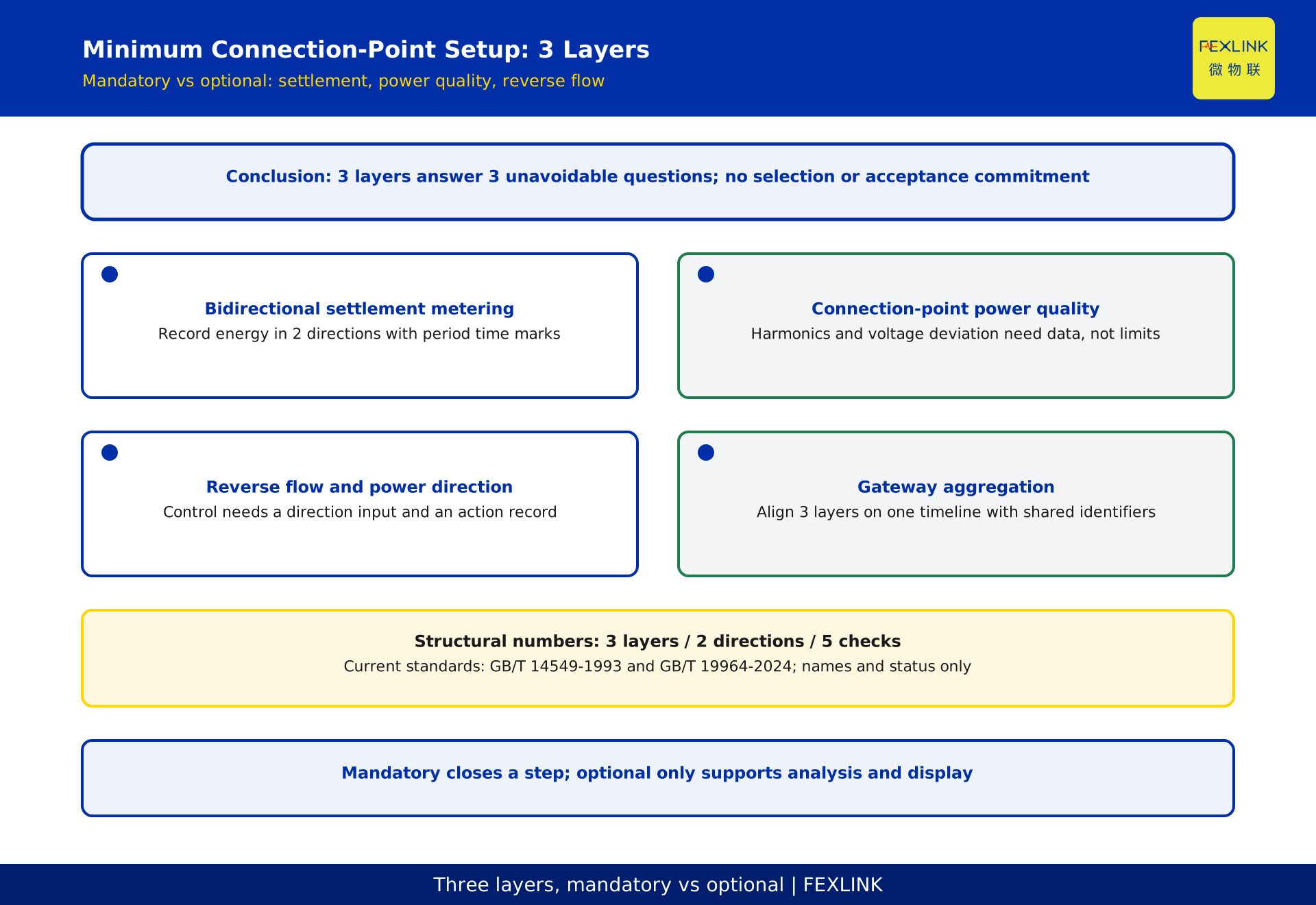
The minimum configuration at a PV connection point has 3 layers: bidirectional settlement metering, power-quality observation at the connection point, and reverse-flow or power-direction monitoring. The test is not how long the equipment list is; it is whether each layer answers a question that cannot be avoided - where settlement energy comes from, whether the waveform injected into the grid can be observed, and whether PV output crosses the agreed power direction. Without the first layer, exported and imported energy cannot be settled separately. Without the second, there is no evidence for allocating responsibility for harmonics and voltage deviation. Without the third, anti-reverse-flow control has no input. This article splits each layer into mandatory and optional items and gives a 5-step checklist for acceptance gaps. Only standard names, numbers, current status and scope are cited; no clause numbers, limits or compliance judgments are given. Everything here is a statement of method, represents no real product, project or customer and constitutes no selection or acceptance commitment. Actual configuration follows the current standard text, project documents, local utility requirements, vendor evidence and measurements at the connection point.
Why connection-point lists swing between two extremes
One extreme is copying another project's list and installing every visible device, spending budget on data nobody reads. The other is fitting only a settlement meter, then being told at acceptance to add more, which costs both schedule and a shutdown window. Both come from the same cause: a connection point is not a single device but an interface where ownership, settlement, dispatch and power-quality responsibility meet. Each party raises requirements from its own vocabulary, and no table says who needs each piece of data and what it is used for.
Start by assigning requirements to purposes. The settlement party needs energy records split by direction. The utility needs observable waveform and voltage-deviation evidence at the connection point. The operator needs power direction as an input to anti-reverse-flow control. Once grouped, mandatory and optional separate naturally: anything a settlement or acceptance step explicitly refers to is mandatory, while anything used only for later analysis, optimisation or display is optional.
The test that separates mandatory from optional
The test is one sentence: if this item is removed, is there a defined step that cannot be completed? A settlement that cannot be closed, a connection-point responsibility that cannot be evidenced, or a control loop with no input all count as cannot be completed. Losing a trend report or a dashboard does not.
Two qualifications apply. First, one device may serve both classes: a settlement meter produces billable energy and also supplies a load profile for operational analysis. Check only its mandatory part against the settlement basis; do not upgrade the whole device because of an extra function. Second, the answer changes with project documents and local utility requirements. Where waveform records are written into a contract annex, they are mandatory; where they are not, collection conditions should still be reserved for observability. This article therefore gives a checking method, not a universal configuration.
Layer one: why bidirectional settlement metering cannot be skipped
The settlement meter answers how much energy moved in which direction. A distributed PV connection point both imports from and exports to the grid, and energy in the 2 directions has entirely different meanings for settlement, incentive accounting and loss allocation. They must be recorded separately rather than accumulated as an absolute value by a single-register meter.
Mandatory here are direction-split energy records, time marks aligned with the settlement period, and traceable reading evidence. The check is direct: compare each settlement clause against the fields the meter can output, and confirm every clause has a matching reading and retention record. If a field is missing, add a meter or a capture channel; do not expect a back-end algorithm to compute a quantity that was never recorded. The ZSA embedded multi-function smart meter plays the direction-split metering role in this layer. Its actual configuration is verified against project circuits and metering requirements; wiring and selection are outside this article.
Layer two: what to observe at the connection point
This layer answers whether the energy injected into the grid can be described. Harmonics, voltage deviation and three-phase unbalance are usually named: all depend on grid background, other equipment on the same bus and wiring, so a figure printed on an inverter datasheet cannot reconstruct actual conditions at the connection point.
GB/T 14549-1993 (Power quality: harmonics in public supply networks) and GB/T 19964-2024 (Technical requirements for connecting photovoltaic power station to power system) are the current national standards commonly cited in this context, according to the national standard information service. This article cites only their names, numbers, current status and a general statement of scope. It provides no specific limits, allowances, clause numbers or compliance judgments; the governing basis is the current standard text, project documents and local utility requirements. The ESE power-quality monitor plays exactly this role of making harmonic responsibility observable; connection method and settings are outside this article.
Layer three: how reverse-flow and power-direction monitoring connect to control
The third layer answers whether output has crossed the agreed direction. Where a project forbids export to the grid, or permits it only under stated conditions, operations need to know power direction in real time and adjust before a boundary is crossed. Two things must be kept apart: monitoring supplies a direction fact that changes over time, while control is the action taken after receiving that fact.
Mandatory are an observable power-direction record at the connection point and evidence of a path carrying that signal to control or alarming. Optional are finer trend analysis, aggregation across connection points and strategy replay. Walk the signal chain during review: where the measurement sits, in what form direction is sent, who receives it, what action follows, and whether that action leaves a record. The mechanism and settings of anti-reverse-flow control belong to a separate article; this one addresses only what must be installed to make direction visible, and does not enter into mechanism or parameter discussion.
Bringing the 3 layers onto one timeline
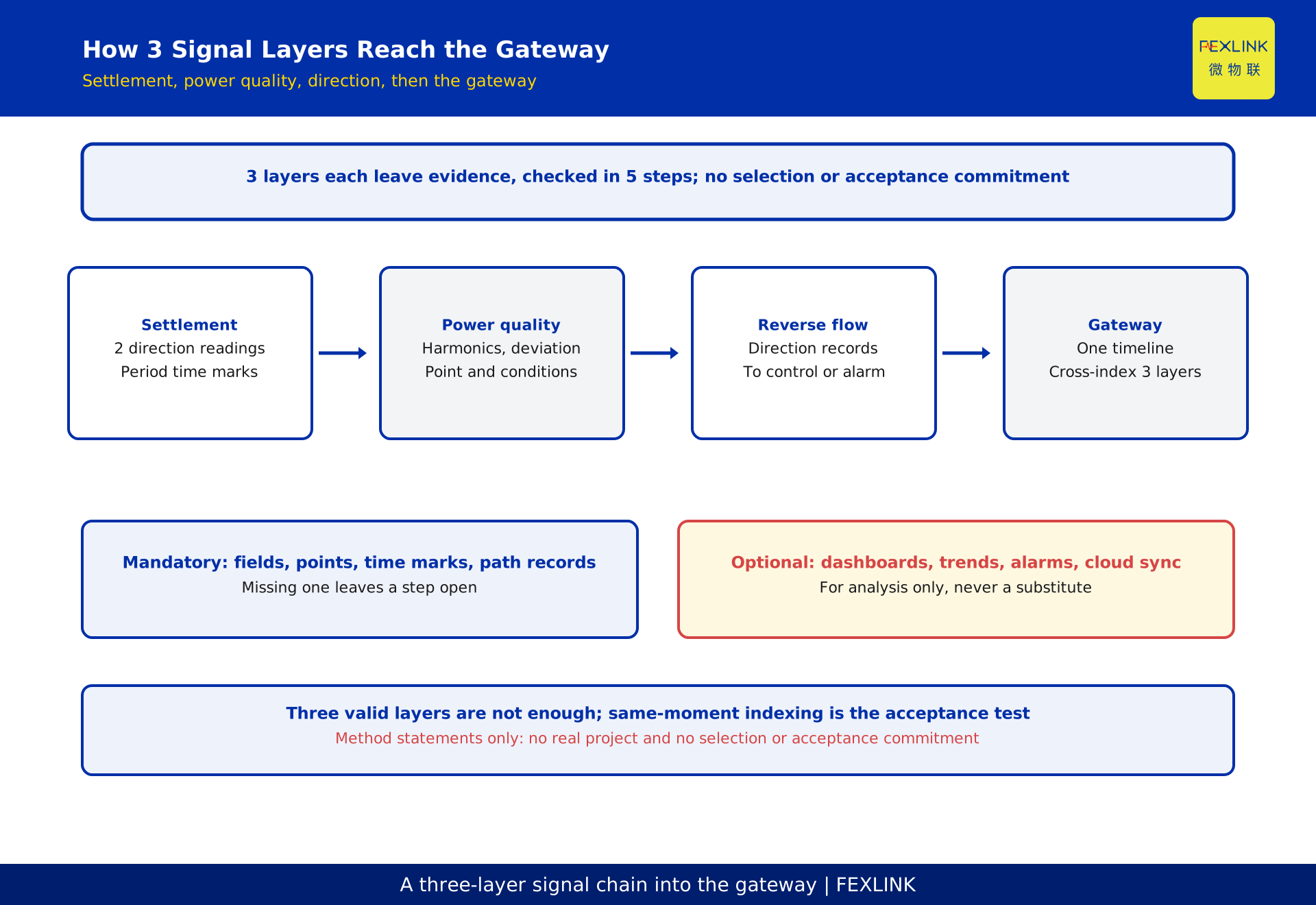
Three valid layers still do not support acceptance on their own. Settlement reads period totals, waveform records depend on time alignment, and direction monitoring is continuous in real time. If each is stored separately with a different time base, an abnormal waveform at a given moment cannot be explained alongside the output direction at that same moment. The gateway does not re-measure anything; it brings the 3 layers under a common timeline and common identifiers, and keeps raw readings from being overwritten.
The ESX intelligent edge computing gateway plays the aggregation and forwarding role here: it organises direction-split energy, waveform quantities and direction records into searchable series, supplying consistent time marks and measurement-point identifiers upstream. Review identifiers rather than interfaces: does one connection point use the same identifier across all three layers, can the same moment be cross-indexed, and can data lost during a network outage be restored?
A mandatory / optional comparison table
The table compresses the test into checkable columns. The evidence column is what must be produced at acceptance, not a device parameter.
| Layer | Question answered | Mandatory (a step fails without it) | Optional (analysis and display) | Evidence to check |
|---|---|---|---|---|
| Settlement metering | How much energy in each direction | Direction-split readings, period time marks, reading evidence | Finer load profiles, remote reading | Clause-by-clause comparison with output fields |
| Power-quality observation | Can the waveform be observed | Records at the agreed point, aligned with conditions | Trend reports, event classification | Measurement-location note and same-period records |
| Reverse flow and direction | Has output crossed the agreed direction | Direction record and a path to control or alarming | Strategy replay, multi-site aggregation | Signal chain and action records |
| Gateway aggregation | Can the three layers be cross-indexed | Common timeline, common identifiers, raw retention | Dashboards, edge alarms, cloud sync | Same-moment index sampling and outage recovery |
How the three device types map onto the 3 layers
Translating a checking basis into devices often goes wrong by ticking a product catalogue instead of filling the layers back in. The right order is to confirm what evidence each layer must retain, then identify which device class can produce that evidence, and only then check the interfaces between devices.
In that order, the ZSA embedded multi-function smart meter corresponds to direction-split metering in the first layer, the ESE power-quality monitor to waveform observability in the second, and the ESX intelligent edge computing gateway to time alignment and forwarding for the third layer and aggregation. Products appear here only as role references, with no selection recommendation, no comparison of merit and no model specifications. Actual configuration must be verified by qualified personnel against project circuits, metering requirements, local utility requirements and vendor evidence; this article constitutes no selection or acceptance commitment.
A 5-step checklist for acceptance gaps
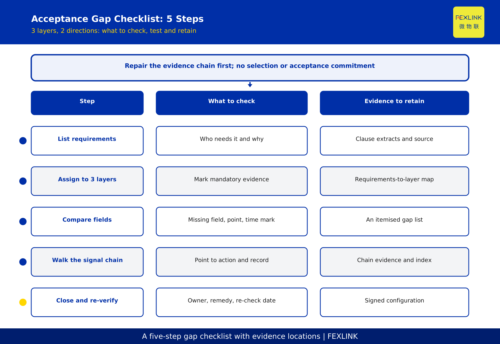
Here is a closing action that can be executed. Step one: extract every clause about connection-point data from project documents, contract annexes and local utility requirements into a requirements table, noting who needs each item and why. Step two: assign the table across the three layers, mark the mandatory evidence for each, and list anything fitting no layer for clarification. Step three: compare the mandatory evidence against the fields and measurement points devices can output; record any missing field, measurement point or time mark as a gap. Step four: walk the signal chain from measurement point to receiver and from receiver to action and retention; any unsupported link is a gap, with particular attention to whether the three layers can be cross-indexed at the same moment. Step five: turn the gaps into a closure table with owner, remedy and re-verification date, and sign configuration confirmation only after re-verification.
This 5-step output is a list with evidence locations, not a purchase order.
Frequently asked questions (FAQ)
Q: Is one bidirectional settlement meter enough to pass acceptance?
Not in general. If project documents and local requirements cover only direction-split settlement, the first layer may suffice; once waveform observability or a traceable power direction is required, evidence from two more layers is needed.
Q: Is power-quality observation only needed when a penalty applies?
That is not a sound test. Observation provides the factual basis for allocating responsibility; assessment is only one use. Even where it is not currently named, measurement points and collection conditions should be reserved at design stage. Whether formal records are required follows project documents and local utility requirements.
Q: With a gateway installed, can the three layers be skipped in review?
No. A gateway aggregates and aligns time; it does not produce settlement readings or waveform records. Measurement points, fields and retention for each layer still need separate review.
Q: Should the year be added after a standard number?
Yes, use the current version in full. The registry standard field carries no year; this article completes it to GB/T 19964-2024 from the national standard information service, while GB/T 14549-1993 already carries its year.
Q: Can this list be used directly as a purchase order?
No. It gives a checking basis and evidence locations, not a product configuration. It represents no real product, project or customer and constitutes no selection or acceptance commitment. Procurement and connection must be verified by qualified personnel against project documents, vendor evidence and measured data.
Scope and limitations
This article is for PV project owners, electrical designers and those preparing grid-connection acceptance. It sets out the 3 layers of minimum monitoring at a distributed PV connection point - bidirectional settlement metering, power-quality observation, and reverse-flow or power-direction monitoring - what question each answers, how to split mandatory from optional, and how to use a 5-step check for acceptance gaps. It is not a reading of inverter parameters, an anti-reverse-flow mechanism or settings guide, a power-quality remediation plan, or a choice of export mode; those have their own articles.
Only the names, numbers, current status and a general statement of scope of GB/T 14549-1993 and GB/T 19964-2024 are cited. No specific limits, allowances, clause numbers or compliance judgments are provided. The comparison table, layer division and checking steps are statements of method; this article represents no real product, project or customer and constitutes no selection, settlement or acceptance commitment. The ZSA embedded multi-function smart meter, ESE power-quality monitor and ESX intelligent edge computing gateway appear only as role references across the three layers. Design, configuration, grid connection and acceptance must be carried out by qualified personnel under the current standard text, project documents, local utility requirements, vendor evidence and measurements at the connection point, and reviewed independently. All deliverables remain pending review; the generator does not self-approve.
Frequently Asked Questions
What to Install at the PV Connection Point
The minimum configuration at a PV connection point has 3 layers: bidirectional settlement metering, power-quality observation at the connection point