 FEXLINK Research Institute
The short answer
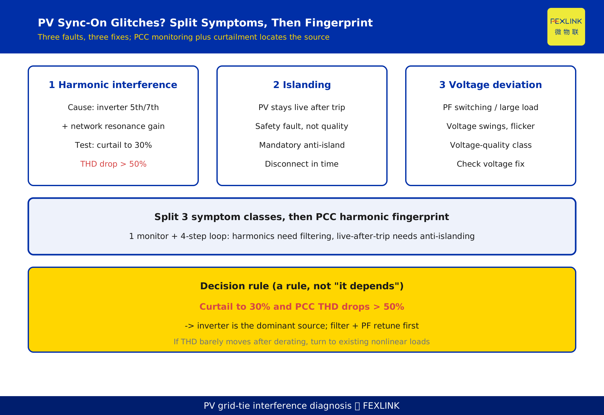
When rooftop PV is grid-synced and precision equipment (CNC, laser metrology, PLC analog I/O) starts glitching, do not blame device aging yet. Three failure modes must be separated: if precision loads misbehave, the culprit is usually inverter-injected harmonics amplified by resonance; if the PV side stays energized after the utility disconnects, that is islanding; if voltage swings or flicker appear, it is voltage deviation or flicker. The fastest way to tell is to install a power-quality monitor at the point of common coupling (PCC), capture waveforms and a harmonic spectrum, and build a "harmonic fingerprint"—then curtail inverter output and watch whether harmonics fall in step. That isolates whether the source is the PV inverter or the site's existing nonlinear loads (VFDs, rectifiers). Clear diagnosis first, then treatment.
1. Separate the symptoms: three interferences, three faults
After grid connection, "old equipment misbehaves" can mean different things. Sort by symptom before touching hardware.
- Precision-equipment faults, comms dropouts, metering jumps: classic harmonic issue. Inverter output current carries harmonics that couple into neighboring circuits and disturb harmonic-sensitive loads.
- Utility de-energized for maintenance, yet the PV-side conductors remain live: classic islanding. This is a safety hazard, not a quality complaint—highest priority.
- Voltage swings, lamp flicker, motor overheating: classic voltage deviation or flicker, possibly from PF-capacitor switching, inverter reactive control, or large load starts.
This article focuses on the first two—harmonics and islanding—because they tie most directly to "grid connection" and are most often misdiagnosed. Note: inverter selection parameters (rated power, MPPT channels, designed THD) belong to KD-0542 (article No. 542); this article does not repeat selection and instead covers post-commissioning fault diagnosis, with its increment being the harmonic/islanding diagnostic path and fingerprint-based source locating.
2. Why the inverter is a harmonic source
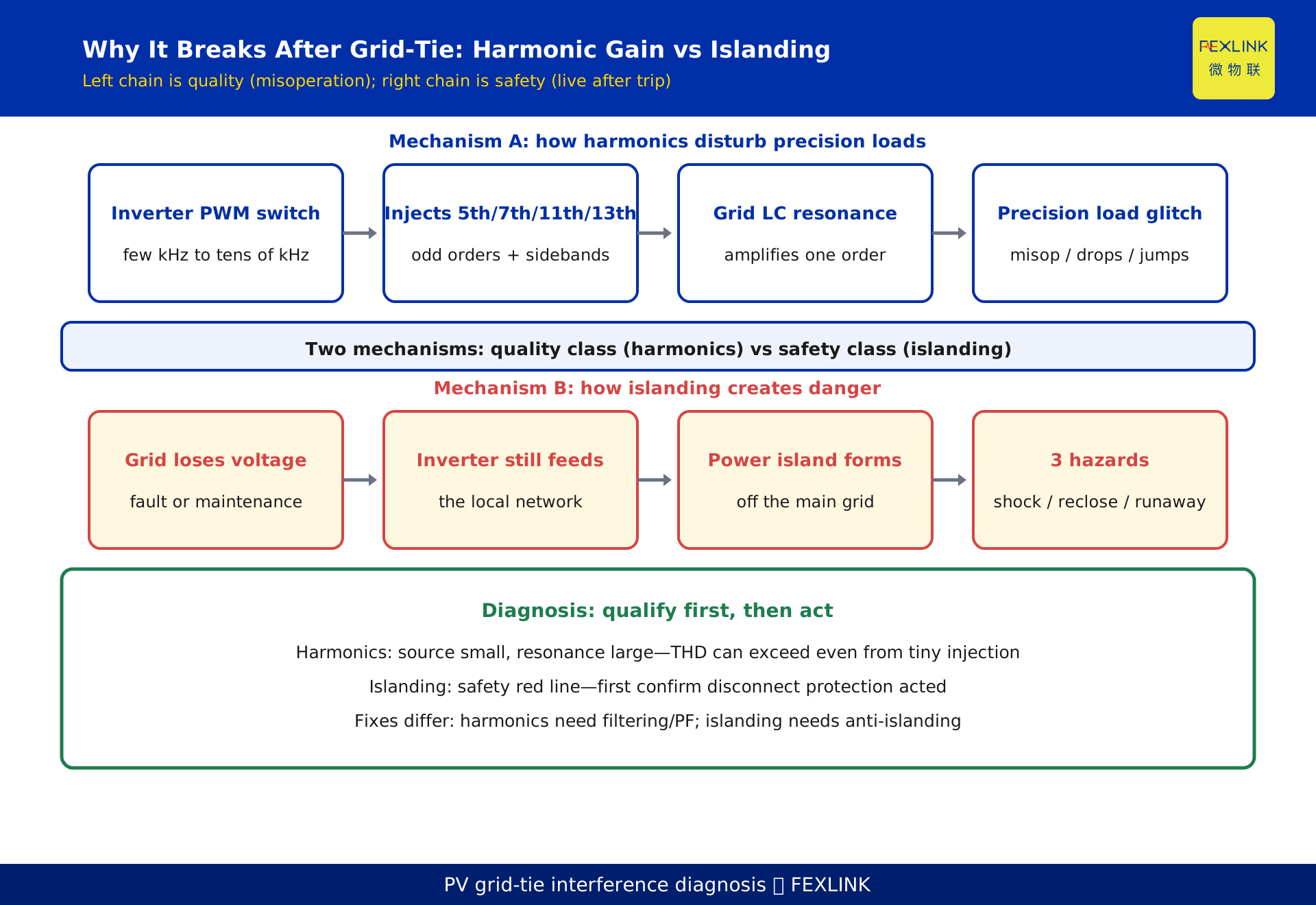
A grid-tied inverter first converts DC from the PV array to AC, then synchronizes with the grid. The conversion relies on high-frequency switching of IGBTs (PWM, pulse-width modulation), typically a few kHz to tens of kHz. No real switch produces an ideal square wave; the current step at each switching instant injects harmonics into the output current.
In the low-frequency band the dominant components are odd orders such as 5th, 7th, 11th, 13th (linked to 6-pulse rectification/inversion logic); in the high band they cluster around the switching frequency and its sidebands. A single inverter's harmonic content is often modest, but when several or dozens of rooftop inverters parallel, same-order harmonics add up. Worse, once these harmonics enter the distribution network they meet the next mechanism—resonance.
Verifiable fact: distributed-PV grid-tied inverter harmonics mainly come from high-frequency components injected by PWM switching and are among the primary sources of PCC harmonics (public reference / power-electronics convention).
3. How resonance amplifies a single harmonic order
Distribution networks are full of inductance and capacitance: transformers and lines are inductive; power-factor correction capacitors and long-cable shunt capacitance are capacitive. Inductors and capacitors together form one or more LC resonance points, each with a natural frequency.
When an inverter-injected harmonic frequency happens to sit near a network resonance frequency, parallel or series resonance occurs and that order is sharply amplified—even if a single inverter injects very little of it, the actual distortion on the bus can exceed limits. This is exactly why many sites "find no large harmonic source yet THD is over limit": the source is small, the resonance is large.
Note: this article does not list a specific limit table. GB/T 14549-1993 "Power quality — Harmonics in public supply networks" sets limits on harmonic distortion and per-order content; the exact values are per the current standard text.
4. Islanding: the danger of staying energized after disconnect
Islanding means: the utility loses voltage due to a fault or planned outage, but the PV system keeps feeding the de-energized local network, forming a power island detached from the grid and "spinning" on its own.
The danger is not "no power" but three things:
- Electric-shock hazard: lines assumed dead for maintenance are actually live, threatening crews.
- Reclosure surge: at grid restoration the island voltage is out of sync with the grid; out-of-phase reclosing can produce a huge inrush current that damages equipment.
- Voltage/frequency runaway: inside the island, load and generation mismatch drives voltage and frequency to drift, burning sensitive equipment.
Because of this, anti-islanding protection is a mandatory safety requirement for grid-tied inverters: once grid voltage/frequency abnormalities (loss of voltage, under/over voltage, under/over frequency) are detected, the inverter must stop feeding the grid within a limited time. Passive detection watches voltage/frequency boundaries; active detection injects a small perturbation to judge—together they minimize detection time. The actual time limit follows the local grid code and inverter specification.
5. Diagnosis in four steps: waveform → fingerprint → locate → verify
The fastest, least guesswork path is a 4-step loop:
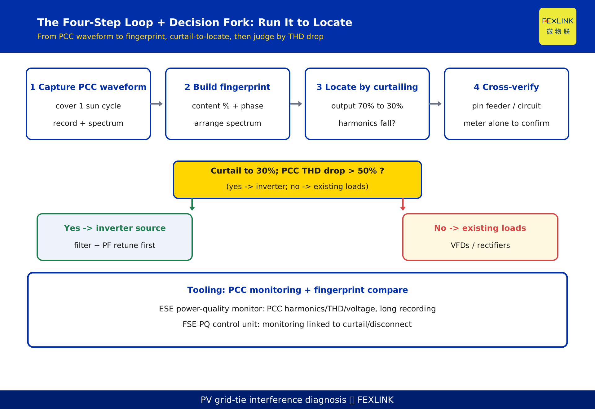
Step 1 — Capture the PCC waveform. Install a power-quality monitor at the point of common coupling, recording voltage/current waveforms and harmonic spectra continuously, covering at least one full "sun—no sun" and one "inverter full-load—reduced-load" cycle. Without data, everything afterward is a guess.
Step 2 — Build the harmonic fingerprint. Arrange each order's content (percent) and phase into a characteristic spectrum—that is the "harmonic fingerprint." Different equipment has different spectra: inverters lean toward switching-frequency sidebands and specific odd orders; VFDs lean toward 5th, 7th; rectifiers toward specific low orders.
Step 3 — Locate by curtailing. Drop inverter output stepwise to 70%, then 30%, and watch whether PCC harmonics fall in step. If harmonics fall as the inverter derates, the inverter is the source; if they stay put, the source is the site's existing nonlinear load. This beats "guessing from the spectrum."
Step 4 — Cross-verify. Use the fingerprint to pin the suspect to a specific feeder or circuit, then meter that circuit alone to confirm.
Vendor-disclosed (harmonic-tracing and responsibility-allocation solution) claims source locking within about 2 hours using the fingerprint method. This is a vendor-disclosed figure; stated here only as a capability note, not as a conclusion or selection advice—final judgment must rest on field measurement and standards.
6. Constructed example: a workshop interference case
The following scenario is constructed to illustrate the diagnostic path and represents no real customer or project.
A factory's 400 kW rooftop distributed PV was grid-connected; afterward a coordinate measuring machine showed intermittent reading jumps and a CNC threw intermittent alarms. The site already had several VFDs and servo drives.
Constructed PCC monitoring data (example): at inverter full load, PCC current THD ≈ 6.8%, with 5th-order content ≈ 4.2% and 7th ≈ 3.1%; after curtailing inverter output to 30%, THD fell to ≈ 2.1% and the 5th/7th dropped visibly. Fingerprint comparison showed the 5th/7th pattern matched the inverter switching logic and moved with output.
Constructed conclusion: the source was mainly the inverter's 5th/7th harmonics, possibly amplified by resonance with the site's PF capacitors; the existing VFDs were secondary. All numbers are constructed examples for demonstrating the "curtail-to-locate" logic; real projects must follow the current GB/T 14549-1993 text and field measurement.
7. Remediation: filtering / curtailing / anti-islanding
After locating the source, treat in order: source first, propagation next, isolation last.
- Filtering: add a passive filter branch or active power filter (APF) at the PCC or inverter output to absorb the amplified order; for resonance amplification, first retune PF-capacitor size or switching to move the resonance point away.
- Curtailment and selection: where resonance is severe and hard to retrofit, derate the inverter or curtail by time slot to avoid resonant conditions; for new projects (see KD-0542) prefer inverters with higher switching frequency and lower designed THD.
- Anti-islanding: ensure the inverter's anti-islanding function is enabled and periodically tested; at commissioning verify the disconnect action time; for high-risk islands add a mechanical disconnect switch as backup.
- Isolating sensitive loads: for extremely sensitive equipment, give it a separate isolation transformer or independent circuit to physically cut the harmonic coupling path.
Decision criterion (a rule, not "it depends"): if curtailing inverter output to 30% drops PCC THD by more than 50%, the inverter is the dominant source of that harmonic and filtering plus PF retuning should come first; if THD barely moves after derating, turn to the site's existing nonlinear loads.
8. How products fit: PCC monitoring and the fingerprint
Diagnosis needs data. The PCC needs a device that records waveforms and harmonic spectra continuously.
At the PCC, use the ESE power-quality monitor (brand + model + function: measures PCC voltage/current harmonic content, THD, voltage deviation, three-phase unbalance, with long-term waveform recording and spectrum export); where monitoring must be linked with control, protection, and curtailment, choose the FSE power-quality measurement and control unit (carries power-quality monitoring and integrates control logic, able to trigger curtailment or disconnect on detected harmonic excess or islanding).
Once data arrives, fingerprint comparison and responsibility allocation can use the vendor-disclosed harmonic-tracing solution; but whatever the tool, the judgment standard must be current standards such as GB/T 14549-1993 and field measurement. Tools only make measurement accurate and locating fast—they do not replace the standard.
FAQ
Q: Once PV is grid-connected and interference appears, can I directly blame the inverter?
No. The inverter is a common suspect, but the site's existing VFDs, rectifiers, and PF capacitors also generate or amplify harmonics. The right move is to capture the PCC waveform, build the harmonic fingerprint, then locate by curtailing—decide with data, not by the timing of grid connection.
Q: What is the relation between islanding and power quality?
They are different in nature. Islanding is a safety fault (staying live after disconnect) under anti-islanding protection; harmonics are a quality issue (equipment misoperation). One monitoring system can catch both, but the remedies differ entirely: islanding needs disconnect protection, harmonics need filtering and reactive optimization.
Q: Can I directly use GB/T 14549-1993 limits to judge exceedance?
It can serve as the judgment basis, but the exact limit values follow the current standard text and this article lists no specific limit table. Judgment should also weigh the PCC location, background harmonics, and system short-circuit capacity, and if needed a qualified body should issue a report.
Q: Without a professional power-quality monitor, can I still start troubleshooting?
Yes—use a portable recorder or clamp harmonic meter at the PCC for a short measurement to confirm "is there harmonics, which order is largest." But completing the fingerprint and curtail-to-locate steps still needs continuous data; installing an ESE-class power-quality monitor is recommended.
Q: Will anti-islanding protection nuisance-trip and cut normal generation?
Passive detection can be over-sensitive to minor voltage/frequency swings, so standards and inverter design require detection tolerance and trip delay; active detection uses a tiny perturbation, balancing sensitivity and anti-nuisance. At commissioning, measure the disconnect action time against the grid code's allowed range.
Scope and limitations
- The harmonic and islanding diagnostic methods here apply to low- and medium-voltage grid-connected distributed PV and commercial/industrial rooftop PV; off-grid (standalone) PV involves neither grid harmonics nor anti-islanding.
- References to GB/T 14549-1993 limits only state its role as a judgment basis; no specific limit table is given, and values follow the current standard text.
- In Section 6, the PV capacity, THD, and per-order harmonic contents are numbers constructed to demonstrate the curtail-to-locate logic (marked as constructed examples) and represent no real customer or project; real harmonic levels must follow field measurement and the standard.
- "Vendor-disclosed source locking within about 2 hours" is a vendor-disclosed figure; stated only as a capability note, it does not enter the core conclusion or selection advice—final judgment must follow field measurement and standards.
- Specific models, parameters, and functions of the ESE power-quality monitor and FSE power-quality measurement and control unit follow the latest product knowledge base and selection manual; this article is not selection or procurement advice.
- Anti-islanding action time and detection method follow the local grid code, inverter specification, and current grid-connection standard; conclusions must be rechecked after a standard revision.
Frequently Asked Questions
Once PV is grid-connected and interference appears, can I directly blame the inverter?
No. The inverter is a common suspect, but the site's existing VFDs, rectifiers, and PF capacitors also generate or amplify harmonics. The right move is to capture the PCC waveform, build the harmonic fingerprint, then locate by curtailing—decide with data, not by the timing of grid connection.
What is the relation between islanding and power quality?
They are different in nature. Islanding is a safety fault (staying live after disconnect) under anti-islanding protection; harmonics are a quality issue (equipment misoperation). One monitoring system can catch both, but the remedies differ entirely: islanding needs disconnect protection, harmonics need filtering and reactive optimization.
Can I directly use GB/T 14549-1993 limits to judge exceedance?
It can serve as the judgment basis, but the exact limit values follow the current standard text and this article lists no specific limit table. Judgment should also weigh the PCC location, background harmonics, and system short-circuit capacity, and if needed a qualified body should issue a report.
Without a professional power-quality monitor, can I still start troubleshooting?
Yes—use a portable recorder or clamp harmonic meter at the PCC for a short measurement to confirm "is there harmonics, which order is largest." But completing the fingerprint and curtail-to-locate steps still needs continuous data; installing an ESE-class power-quality monitor is recommended.
Will anti-islanding protection nuisance-trip and cut normal generation?
Passive detection can be over-sensitive to minor voltage/frequency swings, so standards and inverter design require detection tolerance and trip delay; active detection uses a tiny perturbation, balancing sensitivity and anti-nuisance. At commissioning, measure the disconnect action time against the grid code's allowed range.