 FEXLINK Research Institute
The short answer
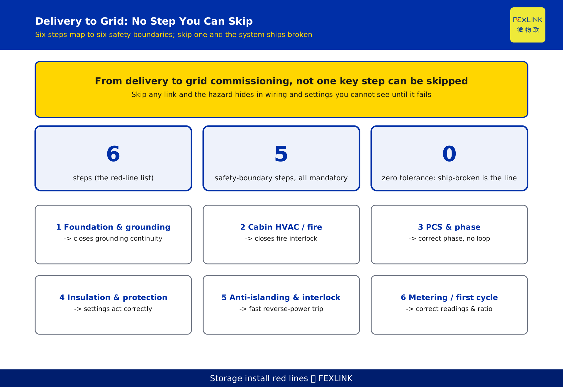
Once a storage cabin arrives on site, from installation to grid commissioning, not one of the critical steps can be skipped: foundation and grounding, battery-cabin installation with thermal and fire wiring, PCS and point-of-common-coupling wiring, insulation and protection verification, charge-discharge joint commissioning with anti-backflow and interlock testing, and grid metering verification. These six steps are six independent safety boundaries. Skip any one and the system may enter service "sick" — the hazard hides in wiring and setpoints you cannot see, silent until it destroys equipment or electrocutes someone. You can resequence steps or run them in parallel to save time, but any step that closes a safety boundary must be performed in full.
1. Why these are red lines, not a checklist
Many teams treat "install to commission" as a sequence of steps to be ticked off in order. A storage cabin is not a normal electrical device. The battery prefabricated cabin integrates cells, BMS, thermal control, fire suppression and the PCS at the factory; the on-site job is not "assemble it", it is to reliably join two safety boundaries — the factory integration boundary and the on-site grid-interconnection boundary.
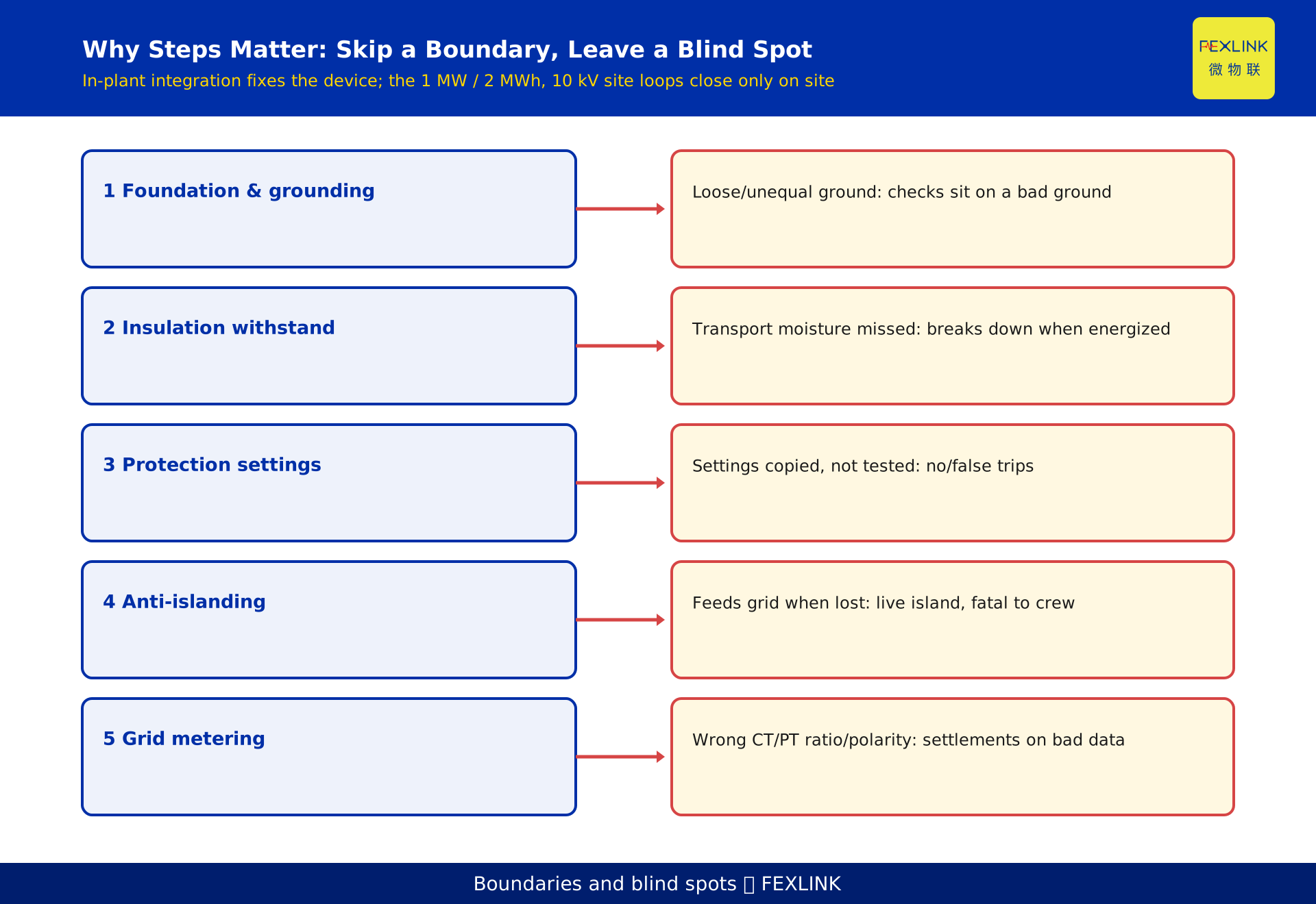
Factory integration covers device consistency and basic function. On-site grid interconnection covers grounding, fire interlocking, phase sequence, insulation and withstand voltage, protection setpoints and anti-backflow — safety loops that can only be closed on site. Each loop broken leaves a blind spot. A step cannot be skipped because it closes one independent safety boundary, not because the process wants a box ticked.
2. Before arrival: foundation and grounding
Every step should start from the ground. Before the cabin is set down, verify foundation load capacity and levelness — and, most often skipped under schedule pressure, re-measure the grounding network resistance.
Factory acceptance was done, but transport, lifting, on-site civil works and moisture all change grounding continuity. Three common failures: the grounding flat steel meets the cabin ground terminal with a loose, under-torqued connection; in a multi-cabin parallel layout the grounding busbars are never bonded into one equipotential system, so each cabin "grounds itself"; and the transformer neutral, the PCS DC side and the battery racks are never unified into one grounding system, leaving lightning or leakage current without a single discharge path.
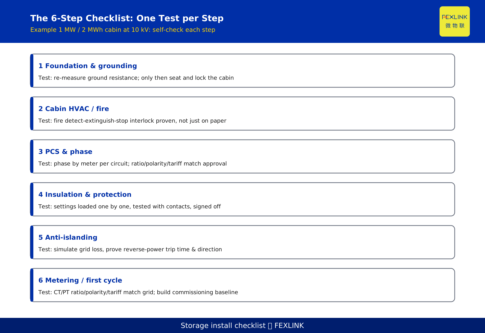
The only test: re-measure grounding resistance on site, and only after it passes may the cabin be set and its ground connection locked. Skip this and every later claim of "insulation OK" or "protection correct" rests on an unreliable earth — equivalent to not measuring at all.
3. Cabin placement and thermal, fire wiring
After placement, the real on-site work is inside the cabin: three wiring sets — thermal-control power, fire detection and interlocking, and BMS communication.
Thermal control is the gatekeeper of battery life. The air-conditioning, liquid-cooling unit and heaters must have an independent, monitored supply; they must not "borrow" power from a ordinary maintenance socket. The rule: the supply circuit carries its own overcurrent and residual-current protection; temperature sensing lines (cell-level or module-level) run separate from power wiring to avoid interference; and every temperature channel is checked for continuity and accuracy after placement, so you never end up with "monitor shows 25 C but it is actually 45 C".
Fire protection is a veto item. Detection (smoke, heat, gas), suppression (Novec or water mist) and ventilation, access control and PCS shutdown must form one interlock chain. The common mistake is treating the fire controller as a standalone device: wire it and leave, without interlocking tests against the BMS, PCS and station controller. In a real fire the detector trips, the suppressant never discharges, the PCS keeps discharging — the consequences cascade. Every link of the fire interlock must be tested in the joint-commissioning stage, not just checked on the drawing.
4. PCS and point-of-common-coupling wiring, phase sequence
The PCS (power conversion system) converts battery DC to AC and feeds the grid. Two things on site admit no sloppiness: phase sequence and point-of-common-coupling identification.
Reverse phase sequence means, at best, the PCS blocks and will not close (a benign fault you catch); at worst, in a parallel or back-feeding layout it causes circulating current and equipment damage. After wiring, verify phase sequence on every circuit with a phase-sequence meter — never by "matching the colours". On the grid side, the disconnect switch, breaker, current and voltage transformers, their positions and ratios, must match the interconnection approval and the drawings exactly. A wrong CT/PT ratio builds every later protection setpoint and metering reading on wrong current and voltage — a fundamental "cannot even measure correctly" error.
Wiring complete is not wiring correct. The deliverable of this step is a point-by-point verification record, not "all wires are connected".
5. Insulation and protection verification
After the cabin and wiring are in place, two verifications stand between you and energization — the last physical safety gate.
Insulation and withstand: test DC and AC sides separately for insulation resistance and dielectric strength, confirming no degradation from transport, lifting or on-site moisture. Protection verification: overcurrent, over/under-voltage, over-temperature, DC insulation monitoring and other setpoints must be downloaded per the setting sheet and tested with real switch signals, confirming action direction and time delay. Many projects "save time" here — copying a template setting without testing — and then the protection fails to act when it should, or trips when it should not.
The test: insulation tests and protection actuations are recorded and signed line by line, not summarised as "verified".
6. Charge-discharge joint test, anti-backflow and interlock
This is the step most often compressed, and the most dangerous. It verifies three things: that charge and discharge work, that anti-backflow and anti-islanding logic are correct, and that all interlocks are reliable.
Anti-backflow (reverse-power protection) is a grid-interconnection red line: when the grid loses voltage or is under maintenance, the storage system must immediately stop feeding the grid, or it becomes a live island that threatens maintenance workers' lives. This logic cannot rely on "factory default parameters"; you must simulate grid loss and reverse-power excursion on site and measure that the system disconnects within the required time. Interlocks include fire-action stopping the PCS, access-open stopping the machine, and full-coverage emergency stops — any one failing is a blind spot.
Skip this step and the system may "charge and discharge fine", but the moment the grid misbehaves it becomes a hazard source.
7. Grid metering and first charge-discharge acceptance
The final step turns "it runs" into "it can be settled and accepted".
Metering: the bidirectional energy meter, the grid-revenue meter and the data collector at the point of common coupling must be wired and calibrated per the metering code; CT/PT ratios, wiring polarity and tariff periods must match the utility side. Otherwise all later charge-discharge revenue and demand management rest on wrong readings. First charge-discharge acceptance: run one complete cycle under load, record capacity, efficiency, temperature uniformity across cabins, protection actions and meter readings, and form the first "commissioning baseline".
That baseline is the foundation for all later operation and reconciliation. Without it, every later "efficiency dropped" or "revenue mismatch" cannot be told apart as equipment versus metering.
8. How this differs from KD-0554: procedure, not acceptance
This article and KD-0554 (storage system standard acceptance) are neighbours but distinct. KD-0554 is about "which standard acceptance items to check before and after commissioning" — an acceptance checklist. This article is about "from arrival to grid connection, which steps cannot be skipped and what blind spots skipping leaves" — a construction and commissioning red line.
The increment: KD-0554 answers "against what standard do we accept"; this article answers "in what order do we build, and what fails if a step is skipped". One is an outcome view, the other a process view. Read together they give "do it right plus verify it right".
9. Where products fit: ESX and EST in the procedure
These steps are not ticked by a person with a clipboard; they turn "invisible boundaries" into "visible data" through edge sensing.
The full-channel check of battery-cabin temperature points can be handled by the EST Multi-channel Temperature Controller (multi-channel temperature intelligent controller): it manages continuity, accuracy and limit alarms for every sensing channel, displays locally and reports upward, so "is the temperature channel truly connected and accurate" can be checked right after placement instead of surfacing as a broken channel at joint commissioning.
Consistency checks across anti-backflow, interlock and metering data can be handled by the ESX Smart Edge Computing Gateway (smart edge computing gateway): on site it aggregates multi-protocol data from PCS, BMS, metering and fire, performs real-time power-direction judgement at the point of common coupling and fast reverse-power trip interlocking — upgrading "anti-backflow logic lives only in the PCS" into "edge-side observable, interlockable and traceable", so the interlock test of step six has data to inspect and records to trace.
Above that, the storage-system installation and grid-commissioning solution consolidates the six steps' verification records into the commissioning baseline.
10. FAQ
Q: Under schedule pressure, which steps can be resequenced and which absolutely cannot be skipped?
What you can optimise is parallelism and pacing; what you cannot skip are the safety-boundary steps. Foundation and grounding, insulation and withstand, protection verification, anti-backflow and interlock, and metering verification are five safety-boundary categories that must be completed in full with records. Cabin placement and PCS wiring are installation bodies that may run in parallel, but no verification action within them may be deleted.
Q: The factory already did acceptance. Why re-test grounding and insulation on site?
Because transport, lifting, civil works and moisture change grounding continuity and insulation level. Factory acceptance proves "qualified when shipped"; on-site re-test proves "still qualified once mounted on your foundation and wired up". The objects differ and cannot substitute for each other.
Q: If phase sequence is wrong, will the system simply fail to grid-connect?
Mostly the PCS blocks and will not close — a benign fault you catch. But in a parallel or back-feeding layout, wrong phase sequence can cause circulating current and equipment damage. Phase sequence must be verified circuit by circuit with a phase-sequence meter, never by eye-balling colours.
Q: Can anti-backflow testing use factory default parameters without on-site measurement?
No. Anti-backflow and anti-islanding are grid-interconnection red lines; the logic must be tested on site by simulating grid loss and reverse-power excursion, measuring trip time and direction. Default parameters were never validated against your point of common coupling and your CT/PT ratios — untested equals unmeasured.
Q: KD-0554 already covers acceptance. Is this article still necessary?
Yes. KD-0554 is the acceptance checklist (outcome view); this article is the construction red line (process view). Checking only against acceptance items while not holding the procedure can produce "all acceptance items ticked, yet a step was skipped" sick commissioning. Together they give "do it right plus verify it right".
Scope and limitations
- The six critical steps discussed here apply to on-site installation and grid commissioning of containerised (prefabricated cabin) electrochemical storage systems; other forms (outdoor cabinet, station-built) may refer to them, but concrete wiring and interconnection requirements follow the interconnection approval and the drawings.
- The cited GB/T 36558-2023 "General Technical Conditions for Electrochemical Energy Storage Systems for Power Systems" is the current standard, covering general technical conditions, tests and inspection requirements for electrochemical storage systems connected to the power system. This article cites only its name, version and scope, and does not address specific clause numbers, limits or test methods.
- The example in this article (a campus 1 MW / 2 MWh storage cabin, 10 kV medium-voltage point of common coupling, PCS rated 1 MW) is constructed to illustrate the procedure and represents no real customer, project or region. Actual capacity, voltage, interconnection point and protection setpoints must follow site survey, interconnection approval and the setting sheet.
- Requirements such as anti-backflow, anti-islanding, insulation withstand, protection setpoints and grounding, and their acceptance thresholds, follow the utility's interconnection approval, the grid-code agreement and the current effective standards; this article makes no commitment to specific thresholds.
- Model numbers, parameters and interfaces of the ESX Smart Edge Computing Gateway and the EST Multi-channel Temperature Controller follow the latest selection manual and product knowledge base; this article is not a selection or procurement recommendation.
- If a standard is revised, the quantitative conclusions here require rechecking; this article does not guarantee the long-term validity of the cited standards.
Frequently Asked Questions
From Delivery to Grid Commissioning
Once a storage cabin arrives on site, from installation to grid commissioning, not one of the critical steps can be skipped: foundation and grounding