 FEXLINK Research Institute
The short answer
An RS485 metering bus that keeps dropping is almost never a failed meter. It is four physical-layer items done wrong: topology (daisy-chain, never a star), termination (120 Ω at the two physical ends only), shield and ground (single-point ground), and node count versus bit rate (electrical loading and distance trade off against each other).
"Intermittent" is the signature of these four, and the classic pair is a star layout with no terminators: the signal reflects off every open branch end, overshoot and ringing pile up, and whether a bit errors depends on where the edge lands relative to the sampling point. That position drifts with temperature, node count and supply voltage — so it works today, fails tomorrow, and works again for a few days after someone reseats a connector.
The order of investigation cannot be reversed: power down and measure A-B resistance (about 60 Ω is correct), then look for branches, then count terminators, then compute loading, and only then suspect interference or the meters.
1. Two different things called "loading"
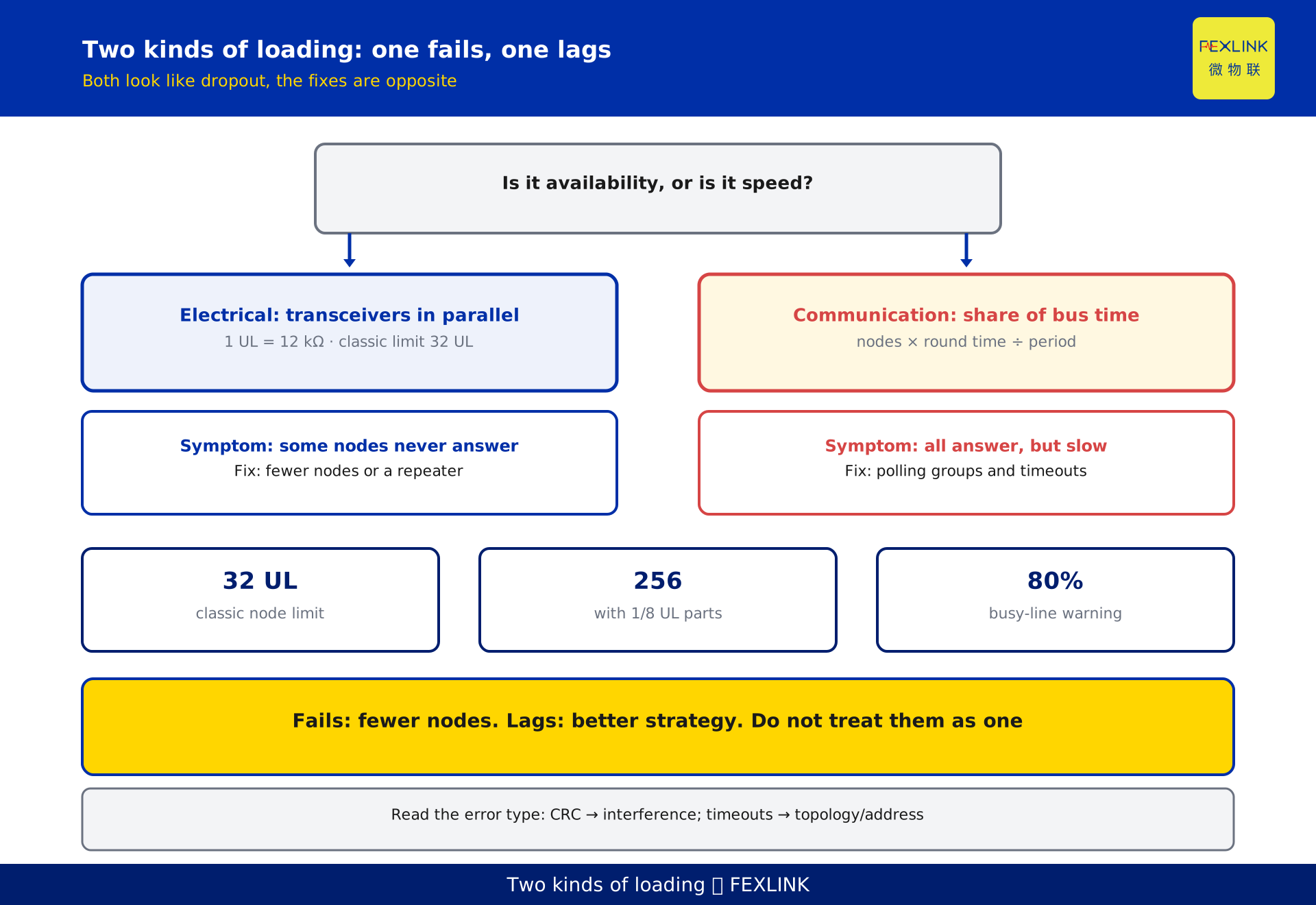
The word loading means two unrelated things on an RS485 bus, and confusing them leads straight to a wrong fix.
Electrical loading is the parallel combination of every transceiver's input impedance, counted in unit loads (UL), where 1 UL = 12 kΩ. The classic standard limit is 32 UL; with 1/8 UL transceivers you can reach 256 nodes. Exceed it and the driver simply cannot swing the bus. The symptom is some nodes never answer, or it fails as soon as the Nth meter is added.
Communication loading is the fraction of time the bus is occupied: nodes × time per round ÷ polling period. Exceed it and everything queues. The symptom is everything answers, but slowly, with occasional timeouts and stale data.
One fails, the other lags; both get called "dropping offline", but the fixes are opposite.
2. The electrical basis: differential, half-duplex, common-mode range
RS485 carries the signal in the voltage difference between two wires, not relative to ground. Common-mode interference appears on both wires and cancels in the subtraction — that is the whole reason it outruns RS232.
Three parameters decide what happens on site:
- Decision threshold ±200 mV. A minus B above +200 mV reads 1, below −200 mV reads 0, and the 400 mV between them is an undefined region. Once attenuation pushes the signal into that region, the receiver starts guessing.
- Common-mode range −7 V to +12 V. This is the ground-potential difference the receiver tolerates. Between buildings or across a substation, the difference can exceed it and the receiver simply cannot see the signal. This failure is routinely misdiagnosed as "interference".
- Half-duplex. One pair carries both directions in turn, switched by DE/RE. Release the driver too soon and the stop bit is eaten by your own turn-around, giving a fixed CRC error.
3. Why it must be a daisy chain: what a star branch does
A daisy chain runs one trunk from the gateway to the last meter; intermediate nodes simply hang on the line.
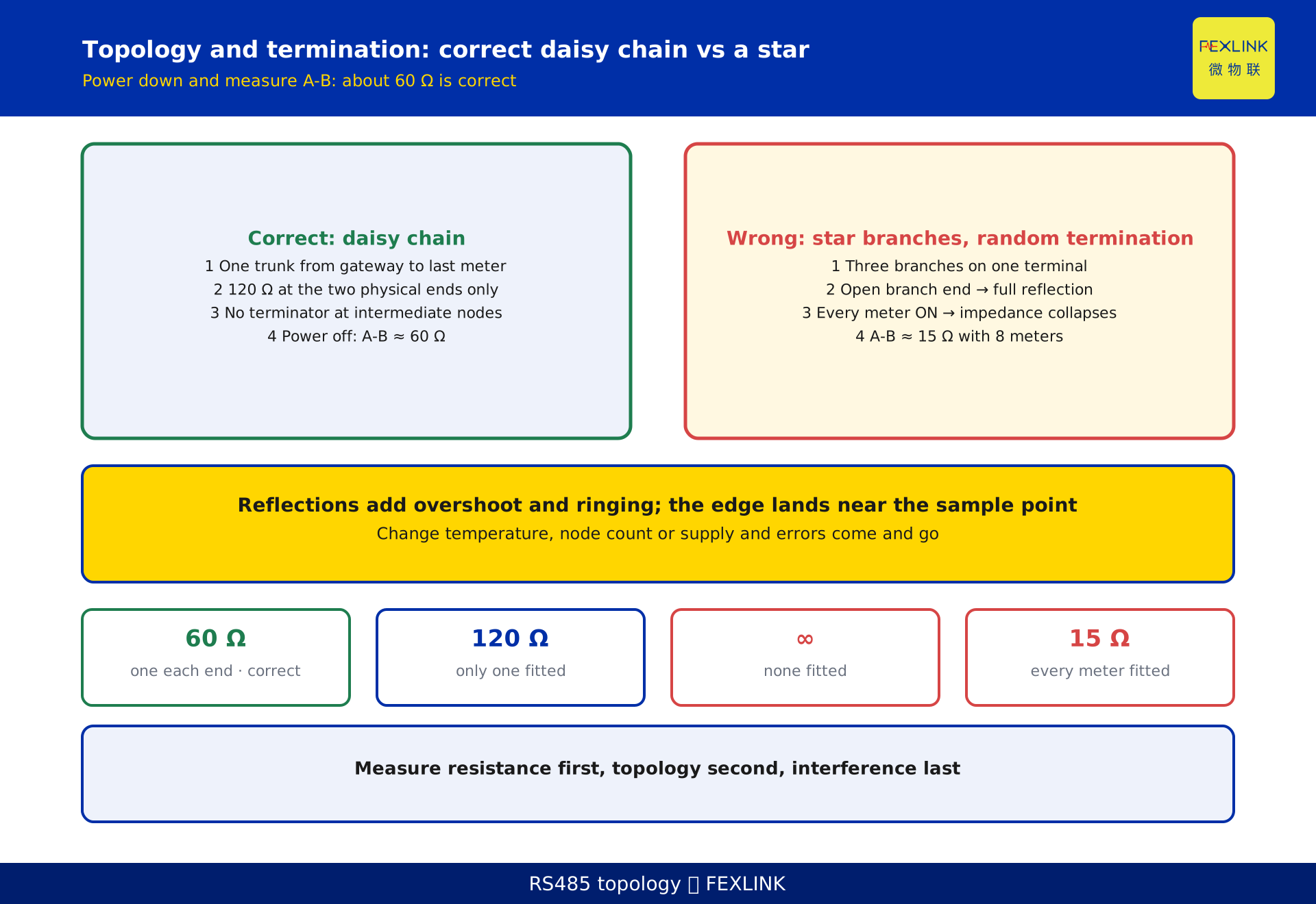
A star or tree is different: every branch is a stub extending from the trunk with an open end. An open end is an impedance discontinuity — the signal reaches the branch tip with nothing to absorb it, reflects fully, and adds to the original. The result is overshoot, undershoot and ringing, with blurred edges.
The critical point is that whether the reflection causes a bit error depends on where the reflected wave lands relative to the sampling instant. That position is not fixed: cable delay shifts with temperature, node count changes bus capacitance, supply variation changes drive strength. Hence the folklore — fine by day, fails at night, fails when the air conditioning starts, fails after two more meters are added.
The answer: one trunk end to end, branches as short as possible (even at low rates, within roughly 1 m; faster buses are stricter). If the layout must be a star, use an RS485 hub or repeater so each branch becomes its own segment — do not twist three cables onto one terminal.
4. Termination: why 120 Ω, why only at the ends
Twisted pair has a characteristic impedance of about 120 Ω. At an end whose impedance does not match, energy reflects; a 120 Ω resistor across the far end makes the cable behave as if it continued forever, absorbing the energy.
Three hard rules:
- One at each physical end — two in total.
- Never at an intermediate node. Each extra 120 Ω in parallel drops the bus impedance from 120 Ω to 60 Ω, then 40 Ω; the driver works harder, the swing shrinks, and errors get worse.
- Fitted means actually fitted. A DIP switch set to ON with no resistor soldered, or a resistor soldered at one end only, is the most common "looks terminated but isn't".
The fastest test: power down and measure A-B:
- 120 Ω at both ends: about 60 Ω (two in parallel).
- Only one fitted: about 120 Ω.
- None fitted: a very high reading or open circuit.
- Every meter fitted: far below 60 Ω — eight meters gives 15 Ω.
Bias resistors appear in parallel, so slightly below 60 Ω is normal, not a fault.
That single reading settles topology and termination in one shot.
5. Bias and fail-safe: the idle bus must not float
With no driver active, the A-B voltage is set by the bias resistors. Without bias, inter-wire capacitance and leakage let the level drift into the ±200 mV undefined region and the receiver output flips at random — the symptom is garbage on an idle bus, frame headers that do not line up, CRC errors.
The fix is fail-safe bias: pull A up and B down through resistors in the hundreds of ohms to a few kΩ, so that idle A minus B stays comfortably above +200 mV.
Two cautions. Many modern transceivers include fail-safe bias, but it is specified only for open, shorted and idle conditions, and can still fail with long cable and high capacitance. And bias resistors are themselves a load: with many nodes, account for them, or you will stabilise the idle state by loading the bus until it stops working.
6. Node count versus distance: you cannot have all three
Node count, bit rate and distance trade off against each other.
Node count follows the transceiver's UL rating, not the marketing. A device advertised as "supports 128 meters" may use 1/4 UL or 1/8 UL parts, or may have bought the number by lowering the bit rate; ask for the UL rating and conditions.
The usual engineering ceiling for distance is 1200 m at up to 100 kbps. Raise the bit rate and distance must shrink; add nodes and bus capacitance rises, edges soften, and the usable distance shrinks further.
A repeater extends distance and adds nodes, but it introduces forwarding delay that eats directly into the polling budget. Data getting slower after a repeater is added is expected behaviour, not a fault.
7. Shield and ground: single-point ground, no ground loops
The shield drains static and high-frequency interference on one condition: it is grounded at one end only, normally at the gateway or master, with the far end left open or capacitively coupled.
Grounding both ends is the most common mistake: the ground-potential difference drives a circulating current, and the shield turns from protection into an interference source — worse than no shield. It shows up most clearly across buildings or substations.
Two more details: the shield must be continuous, bonded 360° at every joint — a pigtail landed on one terminal is no shield above a few tens of kHz; and route away from power cables, crossing at right angles rather than running parallel.
8. Communication loading: how polling strangles the bus
Communication loading = nodes × time per round ÷ polling period. Above about 80% the system starts producing occasional timeouts; above 100% it drops out steadily.
Time per round = request frame + response frame + inter-frame gap. At 9600 bps, 8N1, each byte is 10 bits, about 960 bytes per second, and a frame is tens of milliseconds — payload size is rarely the bottleneck.
The hidden killer is the timeout: one dead node at 500 ms consumes as much bus time as a dozen healthy nodes. With two dead out of sixteen, a round can double, more nodes then time out while queueing, and the whole thing avalanches.
So set the timeout from measured round-trip time — typically two to three times the measured value — instead of typing 1 s into every project.
9. A worked example: 16 meters at 9600 bps
Constructed to illustrate loading; no real project.
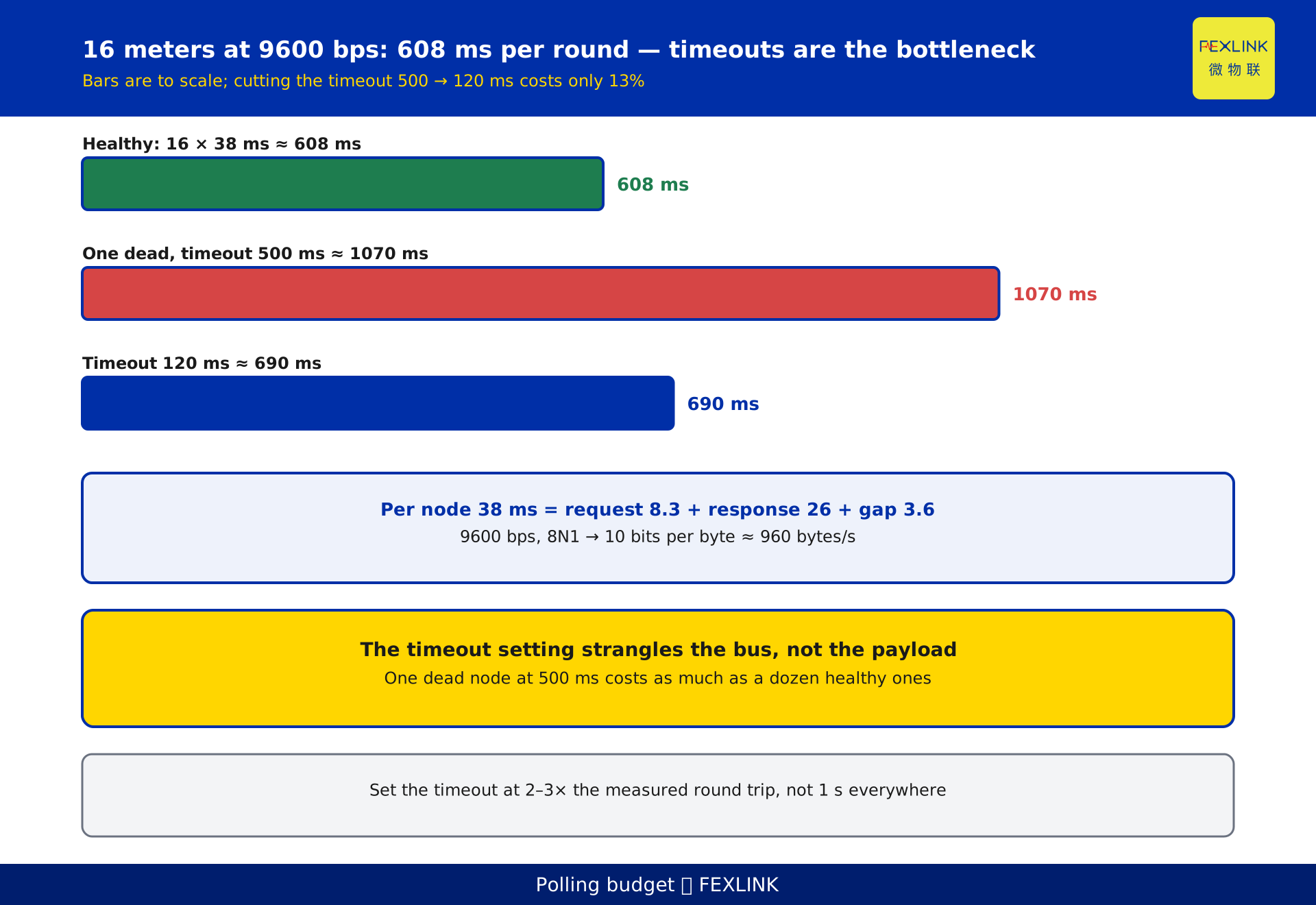
Sixteen multifunction meters sit on one RS485 bus behind a gateway at 9600 bps, 8N1. A Modbus RTU request is 8 bytes, the response 25 bytes, and the inter-frame gap is 3.5 characters.
- 10 bits per byte at 9600 bps → 960 bytes per second.
- Request 8 bytes = 80 bits ≈ 8.3 ms.
- Response 25 bytes = 250 bits ≈ 26 ms.
- Gap 3.5 characters = 35 bits ≈ 3.6 ms.
- Per node about 38 ms; sixteen nodes about 608 ms.
A healthy round is roughly 0.6 s; payload is not the bottleneck.
Now let one meter fail with a 500 ms timeout: the round becomes 15 × 38 + 500 ≈ 1070 ms, close to 1.1 s. Set the timeout to 120 ms — three times the measured 40 ms round trip — and the round is 15 × 38 + 120 ≈ 690 ms, only 13% slower than healthy.
The conclusion: at this scale the bus is strangled by the timeout setting, not by data volume. Cutting the timeout from 500 ms to 120 ms buys far more than raising the bit rate or adding a repeater.
10. Five field checks
In this order, two steps characterise most cases:
- Power down and measure A-B. About 60 Ω is correct; 120 Ω means one terminator; far below 60 Ω means too many; open circuit means none.
- Look at the topology. One trunk end to end, or branches, and how long they are.
- Count terminators. Only the two physical ends, and no intermediate node switched ON by mistake.
- Compute loading. Nodes × UL against the transceiver rating; nodes × time per round ÷ polling period against 80%.
- Check shield and ground. Single-point ground, continuous shield, separated from power.
Read the error type: many CRC errors point to interference and reflection (termination, shield, branches); many timeouts with occasional success point to topology, address conflicts or bit-rate mismatch; nothing at all means check A/B polarity and DE/RE direction control first.
FAQ
Q: Why does it work, then fail, then work again for a few days after reseating a connector?
Reflection or contact problems. Reseating changes contact resistance and branch length, temporarily restoring impedance continuity, but topology and termination are unchanged, so it returns. Measure A-B and look for branches instead.
Q: How many 120 Ω terminators?
Two, at the two physically farthest ends. At an intermediate node they merely add in parallel, lowering impedance and loading the driver. Measuring about 60 Ω across A-B with the power off confirms both ends are fitted.
Q: How many meters can one bus carry?
The transceiver's unit-load rating decides. The classic limit is 32 UL (1 UL = 12 kΩ); 1/8 UL parts reach 256 nodes in theory, but bit rate, distance and cable capacitance constrain that. Leave headroom for expansion.
Q: Does a repeater let me add more meters?
It adds nodes and distance, but it introduces forwarding delay that consumes the polling budget, and it only fixes the electrical layer — star branches and missing terminators remain. Fix the physical layer first.
Q: Should the shield be grounded, at one end or both?
One end, normally at the master or gateway. Grounding both ends creates a ground loop and turns the shield into an interference source. The shield must also be continuous, bonded 360° at joints; a pigtail to one terminal is no shield.
Q: Is a lower bit rate more reliable?
Lower rates tolerate longer cable and poorer high-frequency behaviour and are less sensitive to reflection, but they do not fix missing terminators or star branches, and they lengthen each round. Lowering the rate is a palliative, not a repair.
Scope and limitations
- This article covers RS485 physical-layer topology, termination, bias, shield grounding and loading, applicable to Modbus RTU and other RS485-based metering and monitoring buses. The protocol above RS485 does not change these conclusions.
- The 120 Ω characteristic impedance, ±200 mV threshold, −7 V to +12 V common-mode range, 1 UL = 12 kΩ, 32 UL classic limit and 256-node extension with 1/8 UL parts are general engineering parameters of the RS485 family; specific figures for any transceiver are governed by its datasheet.
- 1200 m at up to 100 kbps is a common engineering ceiling; usable distance depends on cable, bit rate, node count and interference, and must be established by measured error rate. No distance is warranted.
- The 16-node, 9600 bps, 8-byte request, 25-byte response and 3.5-character gap figures are set for easy verification and represent no real project; actual timing must come from a site capture.
- Descriptions of the ESX edge computing gateway and the CW industrial gateway are subject to the latest selection manual and product knowledge base; this article is not a selection or procurement recommendation.
Frequently Asked Questions
Why does it work, then fail, then work again for a few days after reseating a connector?
Reflection or contact problems. Reseating changes contact resistance and branch length, temporarily restoring impedance continuity, but topology and termination are unchanged, so it returns. Measure A-B and look for branches instead.
How many 120 Ω terminators?
Two, at the two physically farthest ends. At an intermediate node they merely add in parallel, lowering impedance and loading the driver. Measuring about 60 Ω across A-B with the power off confirms both ends are fitted.
How many meters can one bus carry?
The transceiver's unit-load rating decides. The classic limit is 32 UL (1 UL = 12 kΩ); 1/8 UL parts reach 256 nodes in theory, but bit rate, distance and cable capacitance constrain that. Leave headroom for expansion.
Does a repeater let me add more meters?
It adds nodes and distance, but it introduces forwarding delay that consumes the polling budget, and it only fixes the electrical layer — star branches and missing terminators remain. Fix the physical layer first.
Should the shield be grounded, at one end or both?
One end, normally at the master or gateway. Grounding both ends creates a ground loop and turns the shield into an interference source. The shield must also be continuous, bonded 360° at joints; a pigtail to one terminal is no shield.
Is a lower bit rate more reliable?
Lower rates tolerate longer cable and poorer high-frequency behaviour and are less sensitive to reflection, but they do not fix missing terminators or star branches, and they lengthen each round. Lowering the rate is a palliative, not a repair.