 FEXLINK Research Institute
The short answer
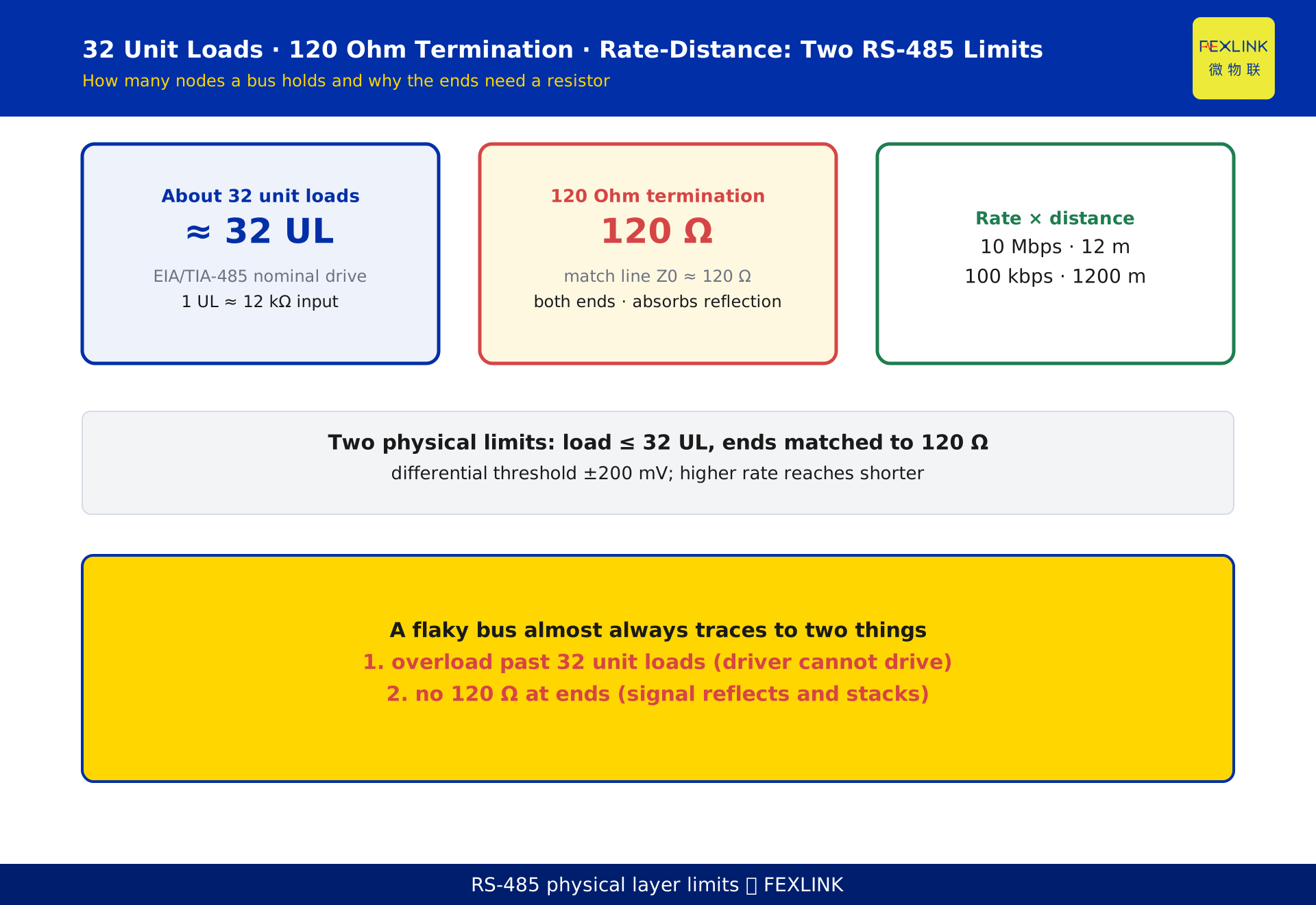
RS-485 is a differential, half-duplex bus. The "32-node limit" comes from the driver's load-driving capability: the EIA/TIA-485 standard nominally requires one driver to drive about 32 unit loads (UL). The "terminator at the ends" exists because a standard RS-485 twisted pair has a characteristic impedance of about 120 Ω; if the bus ends are left unterminated, the signal reflects off the open end and superimposes on the live signal, causing bit errors and intermittent dropouts. Data rate and distance are inversely related. When a site wires dozens of meters onto one bus and gets flaky communication, the physical root cause is almost always overload (too many unit loads) or impedance mismatch (missing or wrong termination).
How A and B wires encode a 1 and a 0
RS-485 does not represent logic by the voltage of one wire against ground. It uses the voltage difference between two wires, A and B. This is why it rejects noise so well: electromagnetic interference from motors and variable-frequency drives couples equally onto both wires as common-mode noise, and the subtraction cancels it out.
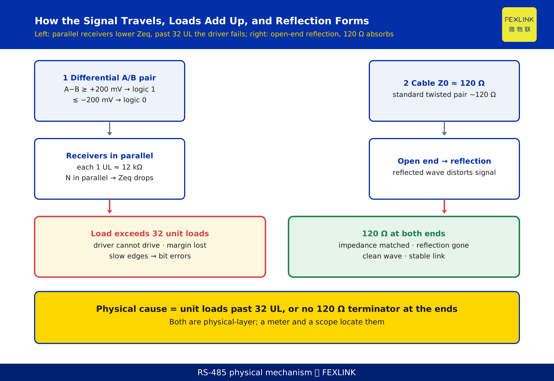
The receiver rule is precise. When the differential voltage A−B is ≥ +200 mV, the line state is interpreted as logic 1 (mark). When A−B is ≤ −200 mV, it is logic 0 (space). Outside that ±200 mV window the receiver makes no guaranteed decision, and the bus is in an undefined state — exactly the zone where bit errors appear.
"Half-duplex" means only one transmitter may drive the line at any instant; every other node must tri-state its output. The master polls, the slaves answer, and that "take turns" discipline is enforced by the protocol layer through master-slave or token arbitration. That part — the message framing and the master-slave rules — belongs to the companion article on the Modbus protocol; this article stays strictly at the physical layer.
Why every device on the bus weighs the others down
Adding one meter to an RS-485 bus is not "one more meter." It is one more load. Every slave receiver presents an input impedance, and all those impedances sit in parallel across the same two wires, pulling the equivalent impedance down.
The driver's capability is fixed: it can source only so much current to push a line that many parallel receivers have loaded down. The heavier the load (more receivers in parallel, lower equivalent impedance), the harder it is to hold the A−B difference above ±200 mV. Edge rates slow, noise margin shrinks, and bit errors arrive. This is the electrical essence of "it works until I add more devices" — and it has nothing to do with the protocol or the software. It is pure physical-layer drive capability.
Where the "about 32 nodes" number comes from
In engineering terms, one standard receiver's input impedance is defined as 1 unit load (UL), and that impedance is about 12 kΩ. EIA/TIA-485 requires that a single driver be able to drive 32 such unit loads in parallel — that is the origin of "about 32." The number 32 is not arbitrary; it is simply "driver capability ÷ single-unit-load."
Three caveats matter. First, 32 is a nominal floor: early devices were designed at 1 UL each, so 32 was the hard ceiling. Second, modern low-load transceivers raise the per-node impedance; a device rated at 1/8 UL can theoretically support 32 ÷ (1/8) = 256 load nodes — the exact ceiling is stated in the device datasheet. Third, the termination resistors and bias resistors on the bus also consume drive capability, so the nodes you can actually hang are often fewer than 32. Treat 32 as an ideal nominal and leave headroom in real designs.
When the signal hits the end of the wire: reflection and the 120 Ω terminator
As the electrical signal travels down the twisted pair, it sees a transmission line with a characteristic impedance of about 120 Ω for standard RS-485 cable. If the bus end is open — no load matched to that impedance — the signal arrives at the end with nowhere to go and reflects back along the wire.
The reflected wave superimposes on the live signal, producing overshoot, ringing, or even polarity reversal at certain points. The waveform the receiver reads inside its ±200 mV window is badly distorted, and the result is bit errors and intermittent loss of communication. The fix is to place a 120 Ω termination resistor at both ends of the bus, so the load the signal "sees" equals the line's characteristic impedance and the energy is absorbed instead of reflected. That is the entire physical story behind "add a resistor at the ends."
One practical note: termination only bites at high speeds, long distances, or when the bus idles. At short distance and low speed the reflection is negligible, and adding termination only burdens the driver. So it is not "always terminate on connect" but "terminate when speed or distance demands it" — verified against the device datasheet and site testing.
The triangle: data rate, distance, and node count
These three quantities cannot all be maximized at once; they trade off against each other.
- Rate vs. distance, inverse. Signal attenuation and distortion rise with frequency, so the farther you go the slower you must run. A typical engineering reference (magnitude only, per the device datasheet): 10 Mbps at roughly 12 m, 100 kbps at roughly 1200 m. If you want to reach meters hundreds of meters away, you drop the baud rate to tens of kbps.
- Node count vs. drive capability, inverse. More nodes means lower equivalent impedance, a more strained driver, and tighter limits on the rate and distance you can sustain.
- Termination vs. rate, positive. The higher the rate, the worse reflection becomes, and the more you need matched terminations at both ends.
So a bus's "capacity" is a budget across all three, not a single number. Fix distance and rate first, then work backward to see how many nodes still fit.
Why sites drop in and out: three overlooked physical causes
Combining the mechanisms above, almost every flaky site traces back to one of three classes:
- Overload. The node count, converted to unit loads, exceeds about 32 (or the driver's rated value). The driver cannot push the line, and the noise margin is exhausted. This is the number-one reason "dozens of meters cause trouble."
- Missing or wrong termination. At high speed or long distance, no 120 Ω at the ends lets reflections stack up into occasional errors; or only one end is terminated, or the wrong value is used (100 Ω, 150 Ω).
- Impedance discontinuity. Over-long stubs, mismatched cable characteristic impedance, or loose connectors all create local reflection points — the classic "works sometimes, drops sometimes" symptom.
All three live in the physical layer. A multimeter for voltages and an oscilloscope for the waveform will locate them; they have nothing to do with whether the Modbus frames are correct.
How to debug an unstable RS-485 bus
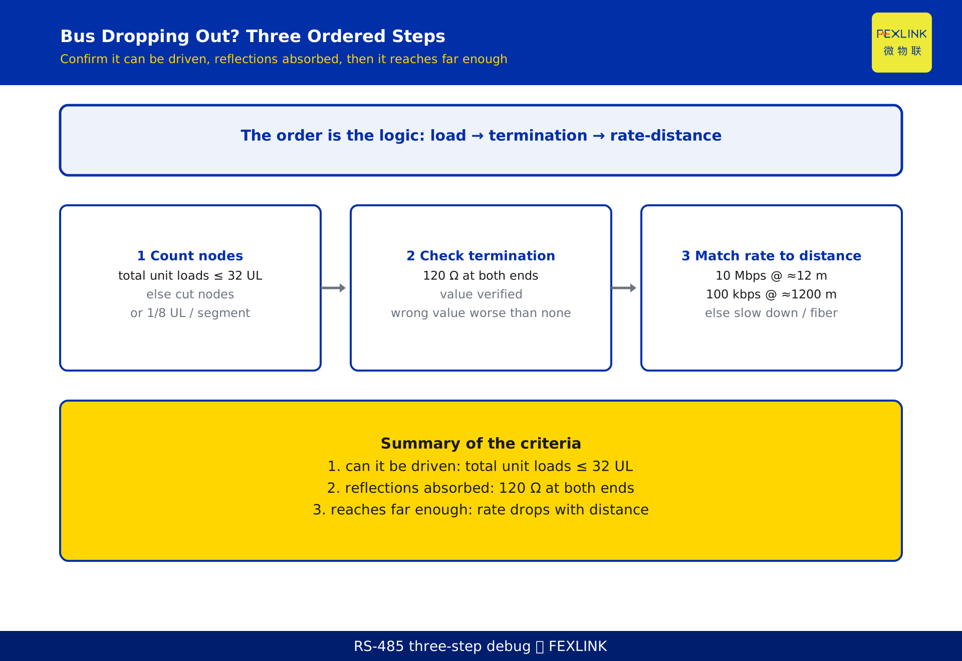
Follow these three steps and most problems are diagnosed within half an hour:
- Step 1 — Count the nodes. Convert every transceiver on the bus into unit loads. If the total exceeds about 32 (or the driver's datasheet rating), first reduce nodes, switch to 1/8 UL low-load devices, or segment the bus. Criterion: total unit loads ≤ driver rating.
- Step 2 — Check termination. At higher speed or longer distance, confirm a 120 Ω terminator at each end with the correct value. Short, slow runs may omit it, but a wrong-value terminator is worse than none. Criterion: 120 Ω at both ends, value verified.
- Step 3 — Match rate to distance. Look up the allowable baud rate for the actual distance (don't force 10 Mbps over hundreds of meters); slow down or move to fiber/repeaters if needed. Criterion: actual baud rate ≤ the distance-allowed value (per datasheet).
The order is the logic itself: first confirm it can be driven, then confirm reflections are absorbed, then confirm it reaches far enough.
How a gateway consolidates multiple RS-485 segments
When meters are spread across areas a single bus cannot serve, or distance exceeds the limit, an industrial gateway that consolidates multiple RS-485 ports is the usual answer. For example, the CW series industrial gateways (such as the CW-C1, CW-C2, and CW-C3 multi-port RS-485 industrial gateways) provide several independent RS-485 interfaces, confining each segment's load and distance problems to its own small network before the gateway aggregates them upstream; the ESX-0223-GR can also act as an edge acquisition node in a multi-protocol setup. The gateway's value is not "breaking the 32-node limit" but splitting one overloaded long bus into several compliant short ones, eliminating the instability at its physical-layer root.
A desensitized example
The following scenario is constructed to illustrate the mechanism and represents no real customer or project.
A switch room ran one RS-485 bus about 800 m long along a cable trench, carrying 40 energy meters. Built "by experience," it had no termination and was set to 9600 bps. After commissioning it dropped out frequently under daytime load and behaved at night.
Applying this article's logic: 40 meters already exceed the 32-unit-load nominal, and the 800 m line's end reflection was unabsorbed. The fix added a 120 Ω terminator at each bus end, then split the bus in two with a CW-C2 multi-port RS-485 industrial gateway in the middle, keeping each segment under 20 nodes. Dropouts fell from several per hour to zero over 30 consecutive days. These figures are a constructed example; a real retrofit must be sized from site survey, datasheets, and measured data.
FAQ
Q: How many devices can RS-485 actually connect?
The nominal standard figure is about 32 unit loads, not "32 devices." If each device is 1 UL, that is 32 devices; with 1/8 UL low-load transceivers the theoretical node count reaches 256. In practice you must also subtract the drive capability consumed by termination and bias resistors, and defer to the device datasheet.
Q: Must I add termination as soon as I connect a bus?
No. At short distance and low speed reflection is negligible, and termination only adds driver load. Generally you terminate both ends with 120 Ω only when speed or distance is high; the exact threshold follows the datasheet and site testing.
Q: Is one 120 Ω terminator at one end enough?
No. Both ends are open before matching, so matching only one end still leaves the other reflecting — the problem is halved, not removed. You need a 120 Ω terminator at each end.
Q: Both ends are terminated at 120 Ω but it still drops out — what else?
It may be overloaded beyond 32 unit loads, mismatched rate versus distance, an over-long stub causing impedance discontinuity, or a common-mode voltage outside the −7 V to +12 V range. Walk through the three steps in the debugging section one by one.
Q: Is RS-485 the same as Modbus?
No. RS-485 is a physical-layer electrical standard (how to send a differential signal over wire); Modbus is the protocol that runs on top of it (frame format, master-slave rules). This article covers only the physical-layer load, reflection, and impedance limits; the protocol frames are handled by the companion Modbus article.
Scope and limitations
- This article addresses RS-485 physical-layer electrical limits — differential half-duplex operation, drive capability, characteristic impedance and termination matching, and the rate–distance relationship — and does not expand on Modbus or other protocol-layer framing and master-slave mechanisms.
- The statements "about 32 unit loads," "120 Ω characteristic impedance and termination," "±200 mV differential threshold," "1 UL ≈ 12 kΩ," and "1/8 UL, theoretical 256 nodes" describe publicly documented interface standards and common engineering knowledge; the per-device unit-load rating, allowed node count, and common-mode range follow the current standard and the device datasheet.
- The rate–distance examples (10 Mbps at roughly 12 m, 100 kbps at roughly 1200 m) are magnitude illustrations only and are engineering experience values, not fixed limits; actual values follow the device datasheet.
- No standard clause numbers are cited in this article; any specific coefficient outside the engineering common knowledge above defers to the current standard, the device datasheet, or the project's technical documentation.
- The site scenario, dropout rate, distance, and node count in the example section are constructed to illustrate the mechanism and represent no real customer or project; a real retrofit must be sized from site survey, datasheet, and measured data.
- The CW-C1/C2/C3 industrial gateways and ESX-0223-GR mentioned here are referenced by their latest selection manuals and product knowledge base; this article is not a selection or procurement recommendation.
Frequently Asked Questions
How many devices can RS-485 actually connect?
The nominal standard figure is about 32 unit loads, not "32 devices." If each device is 1 UL, that is 32 devices; with 1/8 UL low-load transceivers the theoretical node count reaches 256. In practice you must also subtract the drive capability consumed by termination and bias resistors, and defer to the device datasheet.
Must I add termination as soon as I connect a bus?
No. At short distance and low speed reflection is negligible, and termination only adds driver load. Generally you terminate both ends with 120 Ω only when speed or distance is high; the exact threshold follows the datasheet and site testing.
Is one 120 Ω terminator at one end enough?
No. Both ends are open before matching, so matching only one end still leaves the other reflecting — the problem is halved, not removed. You need a 120 Ω terminator at each end.
Both ends are terminated at 120 Ω but it still drops out — what else?
It may be overloaded beyond 32 unit loads, mismatched rate versus distance, an over-long stub causing impedance discontinuity, or a common-mode voltage outside the −7 V to +12 V range. Walk through the three steps in the debugging section one by one.
Is RS-485 the same as Modbus?
No. RS-485 is a physical-layer electrical standard (how to send a differential signal over wire); Modbus is the protocol that runs on top of it (frame format, master-slave rules). This article covers only the physical-layer load, reflection, and impedance limits; the protocol frames are handled by the companion Modbus article.