 FEXLINK Research Institute
The short answer
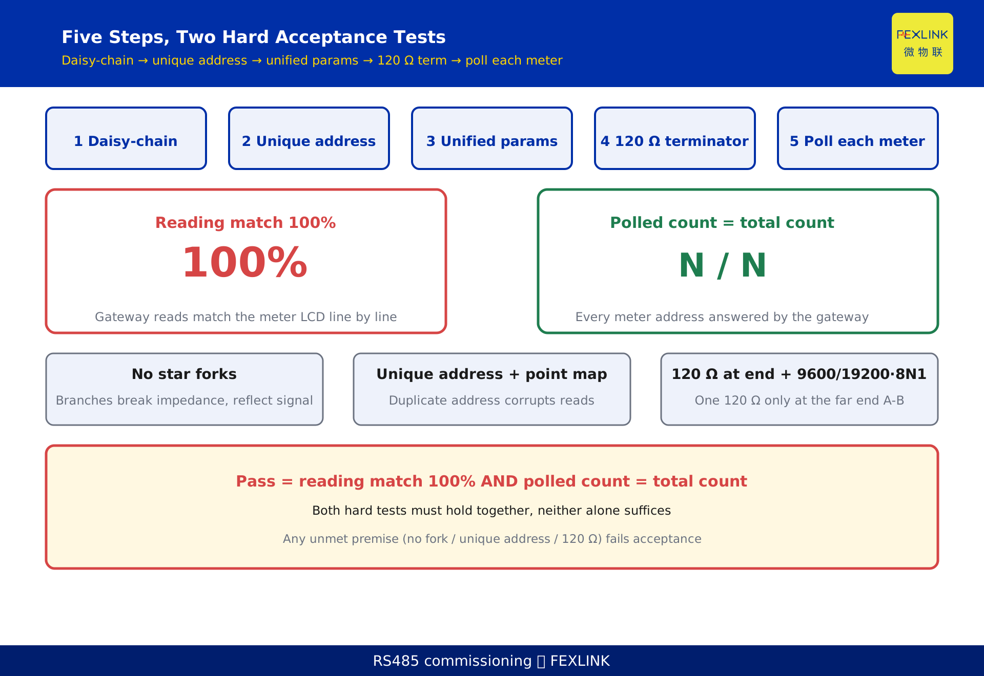
An RS-485 metering bus on site is built and accepted in five steps, and following them avoids the rework that comes from ad-hoc wiring and addressing. Step one: use a daisy-chain topology and forbid star branching. Step two: give every meter a unique slave address and map it to the point table. Step three: unify the bus communication parameters — a common baud rate such as 9600 or 19200 and 8N1 — and fit a 120-ohm termination resistor at the far end to match the bus characteristic impedance. Step four: poll every meter one by one from the gateway. Step five: accept the bus only when every meter address is reachable by the gateway and the readings match the meter's local display. These five steps turn "wire it, address it, commission it, accept it" into a checklist, so the team does not have to re-pull cables or re-address meters later.
1. Why a do-it-by-the-list is needed
The common failure on site is the absence of standard actions: wiring by gut feel, addresses written on the fly, commissioning by trial and error. The result is cables re-pulled, addresses re-assigned, and the schedule slipping. This checklist breaks construction and acceptance into tick-box steps, aimed at field installers, commissioning engineers and system integrators.
It does not replace the neighbouring article on RS-485 physical-layer limits and it does not replace the neighbouring article on meter on-boarding. Its job is to put "what to do on site, what to check at acceptance" onto a list you can actually follow. The added value is the do-it actions and the acceptance criteria, not another explanation of why.
2. Topology first: daisy-chain, no star branches
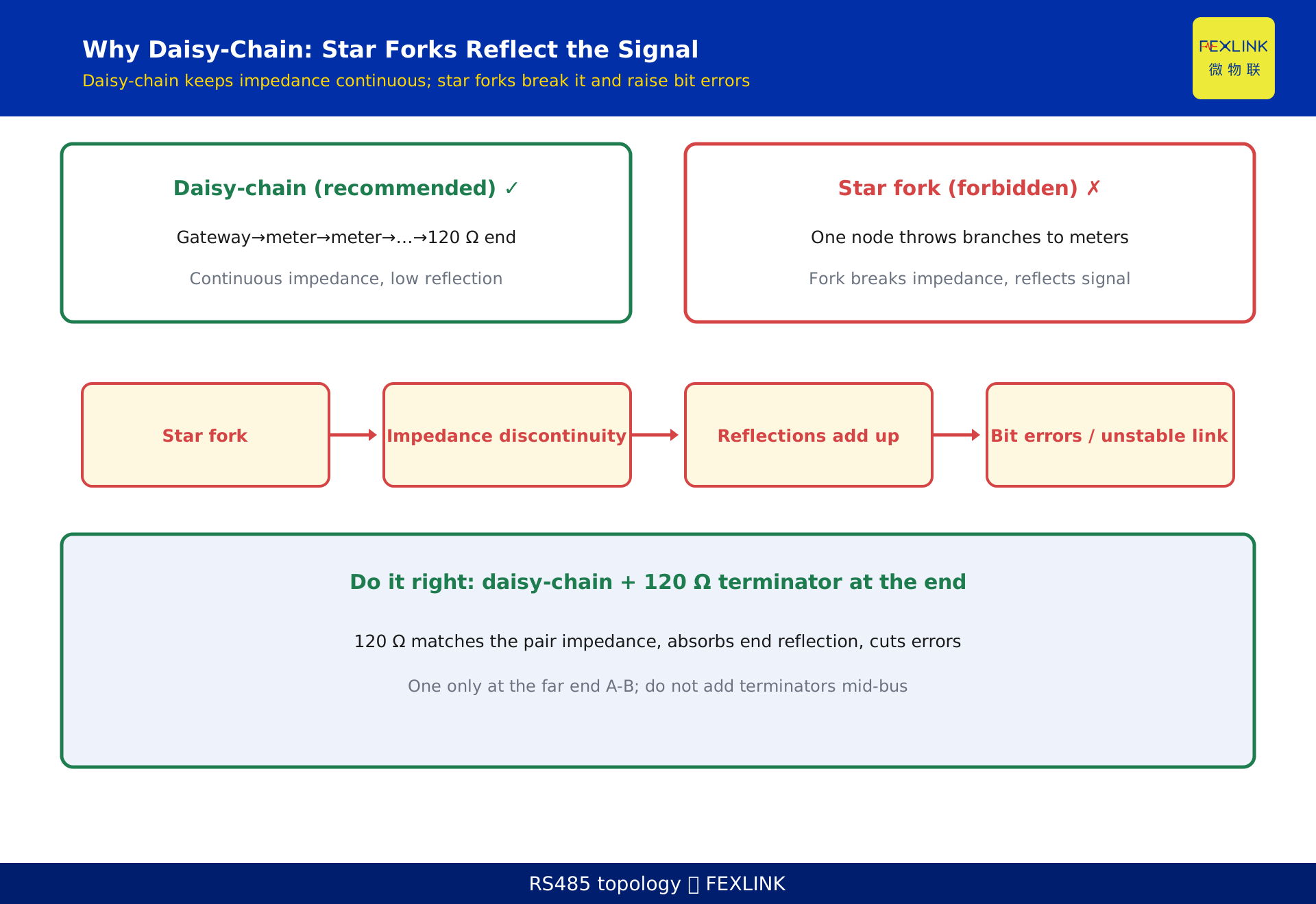
RS-485 is a differential bus. The recommended topology is daisy-chain: start from the gateway A terminal, connect each meter's B terminal to the next meter's A terminal in sequence, and at the last meter fit a 120-ohm termination resistor across A-B. Daisy-chaining keeps the bus impedance continuous along the line, so signal reflection stays small.
Star branching is forbidden: pulling stubs in several directions from one node creates an impedance discontinuity at the branch point, and the signal reflects there. At best readings occasionally corrupt; at worst the whole segment becomes unstable. If the building layout forces a branch, place the branch point at the gateway side and isolate it with a hub or repeater — do not hang meters directly in a star.
In practice the master (gateway) side often also carries a 120-ohm resistor, working with the far-end resistor to match both ends of the bus. Whether to terminate both ends depends on bus length, node count and the device manual, and is decided by on-site measurement.
3. Cable and routing: pick the right wire, avoid interference
Prefer a shielded twisted pair (for example RVSP 2x1.0 or an equivalent shielded twisted pair). The A/B differential pair is twisted together, which gives strong common-mode rejection. When routing: keep strong-current and weak-current in separate trays with as much separation as possible; avoid long parallel runs next to variable-frequency drives and large motors; ground the shield at a single end (usually the gateway side) and never at both ends, or you invite a ground loop.
Cable length and node count are governed jointly by baud rate, wire gauge and on-site interference, and there is no universally valid maximum; a higher baud rate shortens the effective distance. Confirm with on-site measurement and the device manual before work begins. This checklist gives no fixed distance ceiling or node ceiling, to avoid misleading the reader.
4. Address planning: one unique slave address per meter, mapped to the point table
Modbus RTU slaves are distinguished by address. Each meter gets one unique slave address (normally numbered sequentially from 1) and is written into the equipment point table: address, mounting location, meter serial and metered circuit must correspond one to one.
The usual rework starts with addresses: two meters set to the same address collide when the master polls that address, and readings get mismatched; or the address does not line up with the physical install order, so later troubleshooting is guesswork. On site, number the meters in the point table first, set the address from that number second, and photograph the result for the record third — the order matters.
Once an address is fixed, any change goes through a change log, so nobody has to ask "who changed which meter's address" with no trail.
5. Parameters and termination: unified baud rate, 120 ohm at the far end
The whole bus must share one parameter set: baud rate (commonly 9600 or 19200), 8 data bits, 1 stop bit, no parity (8N1), and a consistent slave-address range rule. If any single meter's parameters differ, the master will time out or fail to read it when it gets there.
The 120-ohm termination resistor at the far end matches the characteristic impedance of the RS-485 twisted pair (about 120 ohm in practice), absorbs the signal reflection at the bus end, sharpens the edge and lowers the bit-error rate. Fit exactly one 120-ohm resistor across A-B at the farthest meter; do not add termination at intermediate nodes, or you change the bus loading.
A small reminder: the termination goes across A-B, not from A to ground or B to ground. Wired to the wrong points, it is as good as no termination at all.
6. Step-by-step polling commissioning: from gateway to every meter
Commission in the order "nearest first, confirm each meter": first, power the gateway and set its parameters; second, using a commissioning tool or the gateway's own polling, read live quantities — voltage, current, active power, each shown item by item on the local display of a meter such as the ESX-0223-GR 4G meter — from address 1 outward, meter by meter; third, compare each reading against the meter's local display item by item and confirm they agree; fourth, record each meter's poll response time, and immediately investigate wiring, address or termination for any meter that times out or does not respond; fifth, after every meter is confirmed, run a full poll and tally "reachable count / total meter count".
In one campus retrofit, more than 30 meters were hung on a single RS-485 bus, but the point table was skipped at the start; during commissioning three meters collided on address and two days were lost re-addressing. Using this checklist — point table first, addresses second — a similar project finished commissioning in half a day. That campus is a generic illustration and represents no real customer.
7. The four most common rework traps on site
- Star branching: the signal reflects at the branch point and frames occasionally corrupt. Criterion — be alert the moment you see stubs fanning out from one point.
- Address collision: two meters share an address and readings scramble. Criterion — the point-table number and the physical meter must correspond one to one.
- Missing or mis-wired termination: no 120 ohm at the end, so at high baud rates the edge distorts and the error rate climbs. Criterion — fit exactly one 120 ohm across A-B at the farthest point only.
- Baud mismatch: some meters at 9600, some at 19200, and the master stalls halfway. Criterion — every bus parameter must be checked consistent, item by item.
8. Construction and acceptance checklist (do it)
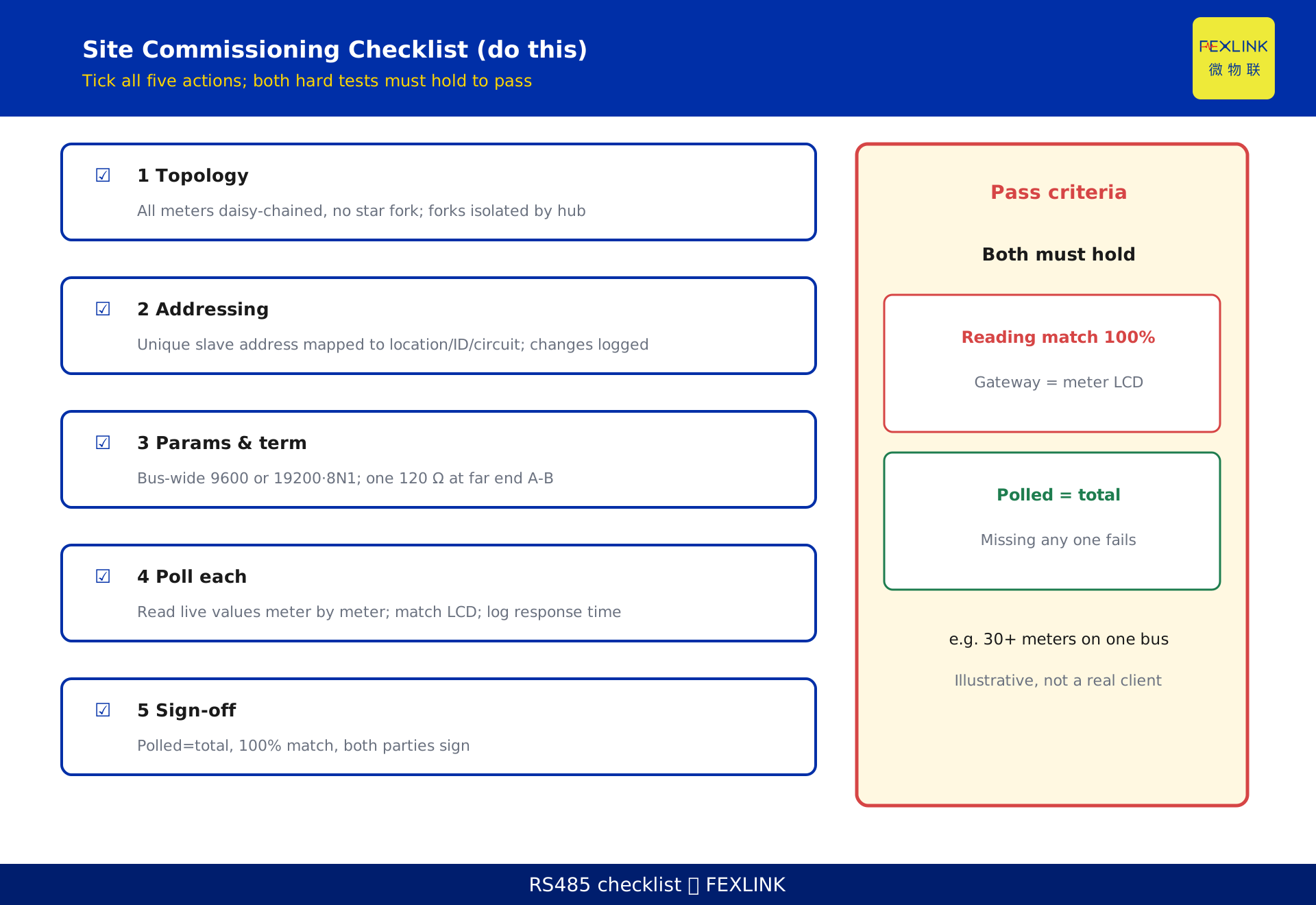
- Topology check: all meters daisy-chained, no star branch; any necessary branch point isolated by a hub.
- Address check: every meter's slave address is unique and corresponds to the point table (location, serial, circuit); address changes are logged.
- Parameters and termination: the whole bus shares one baud rate (9600 or 19200) and 8N1; exactly one 120 ohm sits across A-B at the farthest end.
- Per-meter polling: the gateway reads live quantities from every meter, and readings match the display item by item; record poll response times.
- Acceptance sign-off: the full poll shows "reachable count = total meter count" and a 100% reading match rate; both the installer and the integrator sign.
9. Division of labour with neighbouring articles
This article is the "do-it-on-site construction and acceptance checklist"; its added value is the actions and the criteria. The neighbouring article on RS-485 physical-layer limits covers why distance, node count and baud rate trade off against each other; this article does not repeat the theory, it turns the conclusions into construction actions. The neighbouring article on meter on-boarding covers how the gateway brings meter data onto the platform; this article stops at "the field bus is up and the readings agree", and hands platform integration to that article. Together the three cover the full chain of "theory — field construction — on-boarding".
FAQ
Q: Why fit a 120-ohm termination resistor at the bus end?
Because the characteristic impedance of the RS-485 twisted pair is about 120 ohm in practice, and a 120-ohm resistor at the end matches that impedance, absorbs the signal reflection, sharpens the edge and lowers the bit-error rate. Without it, at high baud rates the reflected signal at the end superimposes and readings misread. Fit exactly one at the farthest end; do not add it at intermediate nodes.
Q: What happens if an address is set twice?
Two meters sharing one slave address collide when the master polls that address, and the readings may be mismatched or simply unreadable. Troubleshooting then means powering meters down one by one to locate the clash. So the address must be unique and mapped to the point table: number first, set second, record third.
Q: Does the gateway end also need a termination resistor?
In practice the master end often carries a 120-ohm resistor too, matching both ends together with the far-end resistor, but whether to terminate both ends depends on bus length, node count and the device manual. The rule of thumb is "match both ends, add none in the middle", decided by on-site measurement; this checklist does not prescribe a fixed method.
Q: Baud rate 9600 or 19200?
It depends on bus length and interference: for long distance or heavy interference prefer 9600 for a steadier error rate; for short distance, many nodes and faster polling consider 19200. The key is that the whole bus must be consistent, never mixed. The actual ceiling follows the device manual and on-site measurement.
Q: What is the hard pass standard at acceptance?
Two clauses: first, every meter address is reachable by the gateway (reachable count = total meter count); second, the gateway reading and that meter's local display agree item by item. Both must hold at once; missing either one is a fail.
Scope and limitations
- This checklist applies to field construction and acceptance of metering and acquisition networks using RS-485 (master-slave serial protocols such as Modbus RTU); other physical layers or wireless schemes may borrow the thinking but must not copy the specific parameters.
- The numbers cited here (120-ohm termination, 9600/19200 baud, 8N1, daisy-chain topology, unique slave address, polling acceptance) are statements of common engineering practice, sourced as engineering practice or public material. They are not mandatory standard values and do not constitute a fixed distance or node ceiling.
- The example parameters in this article (such as the illustrative address numbers, the generic scenario of more than 30 meters, and the reading comparisons) are constructed to explain the method and represent no real customer project. Actual cable selection, distance, node count and communication stability must follow site survey, device manuals and measurement.
- The related-standards field is empty; the article carries zero standard-number references, zero clause numbers and zero conformance claims. Any quantified conclusion tied to a specific standard should follow the currently valid version.
- The mention of CW-C1/C2/C3 industrial gateways is only a role comparison as "edge access gateways"; product names and capabilities are stated on the vendor's disclosed basis and do not enter the selection or acceptance criteria. This article is not a selection or procurement recommendation.
Frequently Asked Questions
Why fit a 120-ohm termination resistor at the bus end?
Because the characteristic impedance of the RS-485 twisted pair is about 120 ohm in practice, and a 120-ohm resistor at the end matches that impedance, absorbs the signal reflection, sharpens the edge and lowers the bit-error rate. Without it, at high baud rates the reflected signal at the end superimposes and readings misread. Fit exactly one at the farthest end; do not add it at intermediate nodes.
What happens if an address is set twice?
Two meters sharing one slave address collide when the master polls that address, and the readings may be mismatched or simply unreadable. Troubleshooting then means powering meters down one by one to locate the clash. So the address must be unique and mapped to the point table: number first, set second, record third.
Does the gateway end also need a termination resistor?
In practice the master end often carries a 120-ohm resistor too, matching both ends together with the far-end resistor, but whether to terminate both ends depends on bus length, node count and the device manual. The rule of thumb is "match both ends, add none in the middle", decided by on-site measurement; this checklist does not prescribe a fixed method.
Baud rate 9600 or 19200?
It depends on bus length and interference: for long distance or heavy interference prefer 9600 for a steadier error rate; for short distance, many nodes and faster polling consider 19200. The key is that the whole bus must be consistent, never mixed. The actual ceiling follows the device manual and on-site measurement.
What is the hard pass standard at acceptance?
Two clauses: first, every meter address is reachable by the gateway (reachable count = total meter count); second, the gateway reading and that meter's local display agree item by item. Both must hold at once; missing either one is a fail.