 FEXLINK Research Institute
The short answer
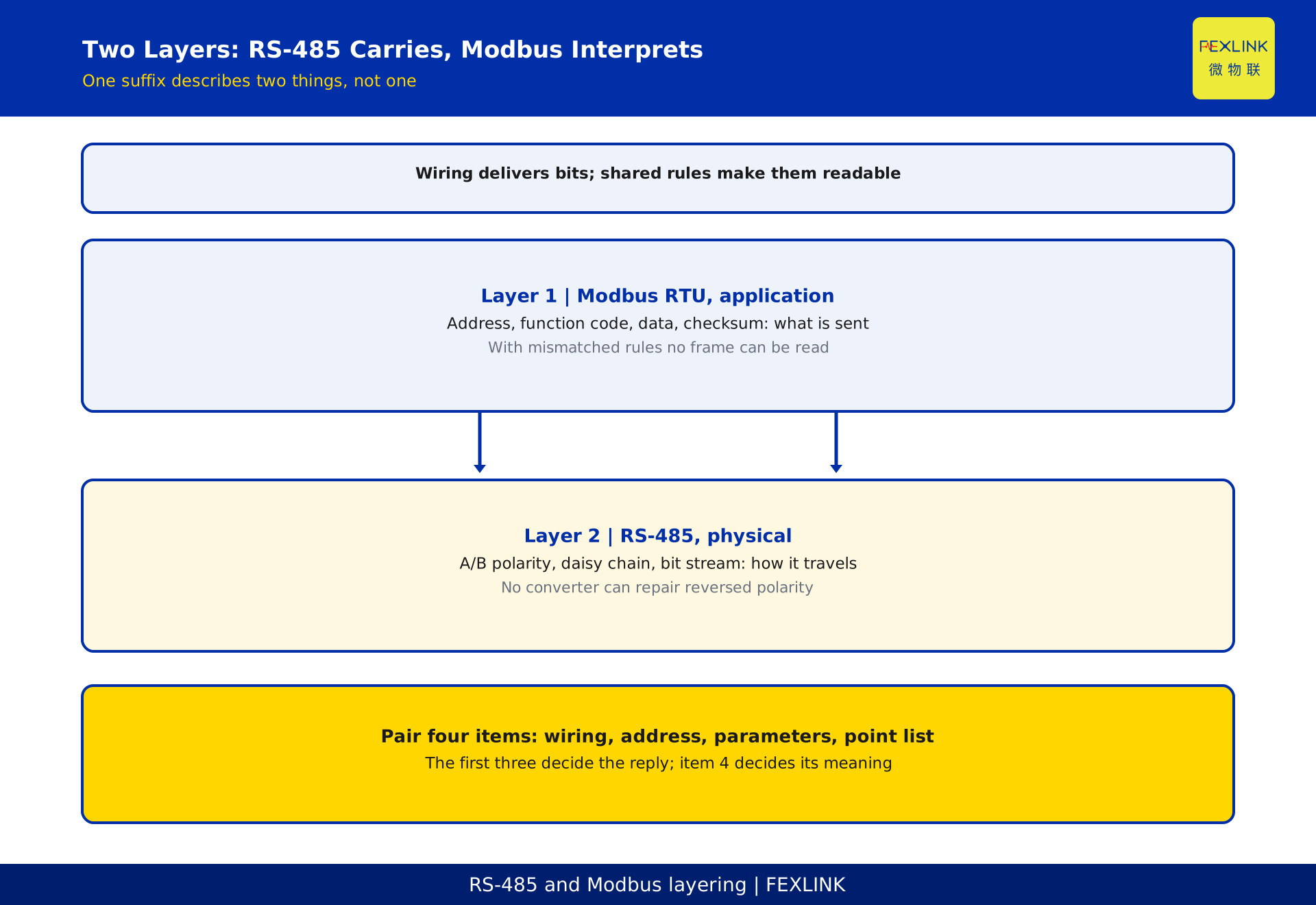
A suffix like "-R (RS485/Modbus)" describes two different layers. RS-485 is how a pair of differential wires carries bits; Modbus RTU is the rulebook that turns those bits into a question and an answer. Sound wiring only guarantees that bits arrive; a shared rulebook makes them readable.
Modbus RTU is a master-slave protocol. One master, usually a gateway, issues every request; slaves answer only when addressed and never report on their own. The master polls one device at a time, uses a function code to name the register area and starting position, and gets a reply with a checksum. Baud rate and frame format, meaning data bits, parity and stop bits, must match across the bus; one mismatch and even bit boundaries cannot be recovered.
This article gives one checkable rule: separate "no connection" from "wrong value". Three settings decide whether any reply arrives, namely wiring, address and communication parameters; the fourth, the point list, decides what the number means. Pair those four items and debugging turns from waiting for a vendor visit into an ordered elimination.
1. Separate the two layers: RS-485 carries, Modbus interprets
RS-485 defines the physical layer. Two differential conductors, labelled A and B, must keep the same polarity at every node, and devices attach in a daisy chain. It delivers a stream of bits and nothing more: it does not say what those bits represent, and it does not decide who may transmit.
Modbus RTU defines application-layer frames and behaviour: who transmits first, to whom, which action is requested, how data is arranged, and whether a frame arrived intact. It is not tied to one kind of wire.
Two misreadings come from collapsing the layers. "The RS-485 cable is connected, so Modbus works" ignores that a cable is only a physical path; with mismatched rules no frame can be read. "A protocol converter will fix unstable communication" ignores that reversed A/B polarity is a wiring fault no translation can repair. Locate the layer first, then decide whether to touch wires or configuration.
2. One master, many slaves
A Modbus RTU segment normally has one master and several slaves. The master walks its address list; a slave responds only when it hears its own address, and unaddressed devices stay silent. Broadcast exists, but reading measurements does not use it.
So two slaves never have a legitimate reason to speak at once. If two devices share one address, the master receives overlapping frames in the same poll and the checksum fails. Two devices work intermittently while the others stay healthy, which looks more like an address collision than two failed meters.
3. Inside a request and a reply
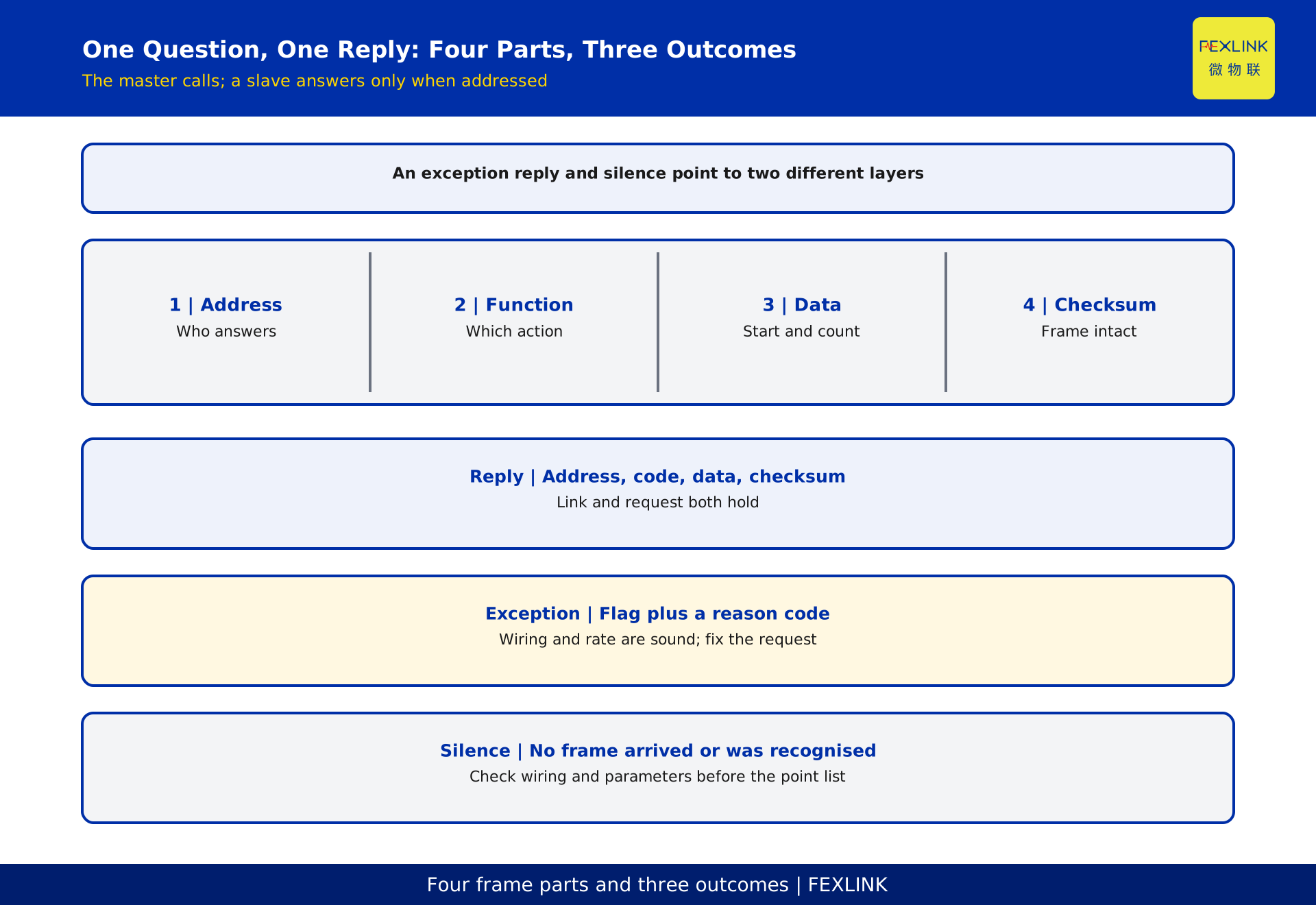
A request frame has four parts: the slave address, a function code naming the action, a data field saying where to start and how many positions to read, and a checksum. The reply echoes the address and function code, adds a byte count and the data, and ends with its own checksum.
The useful distinction is between a reply, an exception reply and silence. If a slave understood the request but cannot carry it out, because the position does not exist or the code is unsupported, it returns an exception frame with a reason code. Silence means the frame never arrived or was never recognised.
So the symptom can be read layer by layer: an exception reply says the wiring, address and rate are broadly sound and the problem lies in the request; no reply at all sends you back to the physical layer and the parameters, not to the point list. Checksum failures point to wiring quality, interference or truncated frames.
4. Registers are addresses, not values
A register is a numbered storage position inside a device. The protocol specifies "read position N, read M positions" and nothing about what sits there. Treating "we got a number" as "we got the right number" is the most expensive assumption in commissioning.
Modbus divides data into four areas: coils, readable and writable bits; discrete inputs, read-only bits; holding registers, readable and writable words; and input registers, read-only words. Meter measurements normally live in the last two. Using a holding-register action against the input-register area usually produces an exception rather than a plausible number.
Numbering has two conventions: frames commonly use an offset counted from 0, while manuals number positions from 1, so the same position differs by one. The point list puts position, meaning, unit, data type, scaling factor and byte order into writing. Without it, the words returned by the master are just numbers, not engineering values. Capturing frames and building the list belongs to a neighbouring article.
5. Choosing the function code
A function code is the action number in the frame: read coils, read discrete inputs, read holding registers, read input registers, write a single register, write multiple registers. It names an action on a type of area, not a device: the address locates a device, the function code locates an action type.
The two actions used most on site are reading holding registers and reading input registers: the first covers writable parameters and settings, the second read-only measurements. Which area holds energy, and at which position, is stated only in that meter's point list.
Reading a run of consecutive positions in one request saves poll time. If the point list scatters values across non-adjacent ranges, split the reads; one long read pulls in unrelated positions. Never approach read-only values with a write action, and confirm a position is writable before writing it. A wrong function code normally yields an exception reply, not a slightly wrong value.
6. Four settings that must match
Wiring. A to A, B to B, the same polarity at every node, chained rather than branched. Here we only judge continuity and polarity; cabling practice, termination and distance limits belong to the physical-layer article.
Address. Every slave needs a unique one. Check the address register before adding a device, and avoid a collision with an existing device or the broadcast address. A wrong address shows up as the master asking one device while another answers, or as nobody answering.
Baud rate. It sets how many bits travel per second, and both ends must use the same setting; one step apart and the slave cannot even find a bit boundary, which looks like a dead device. Faster is not automatically better. Take the value from the device manual and the existing bus convention.
Frame format. Data bits, parity and stop bits must match the master too. Correct rate with wrong parity often produces a soft fault where reads succeed occasionally and time out most of the time. The first three settings decide whether a complete frame arrives; frame format decides whether it can be decoded.
7. The point list is the last mile
A reply with no exception only proves that the link and the action are right. Whether the number is right depends on four columns agreeing.
Column one is the position and its counting convention: an offset from 0 against a manual numbered from 1 reads the neighbouring position. Column two is data type and width: decoding a two-position value as one position gives a number that looks reasonable and is entirely wrong. Column three is unit and scaling factor: the same words under a different factor produce a result off by a clean multiple, and that tidy error almost always points at the point list. Column four is byte order: reversed ordering gives an obviously impossible number without raising a communication alarm.
The order is fixed: first ask whether a reply exists, then whether the reply is an exception, and only then what the value means. Skipping the first two steps can turn one wiring fault into three days of register comparison. With the four columns undocumented, no report should be issued.
8. Worked example: only 9 of 12 meters come online
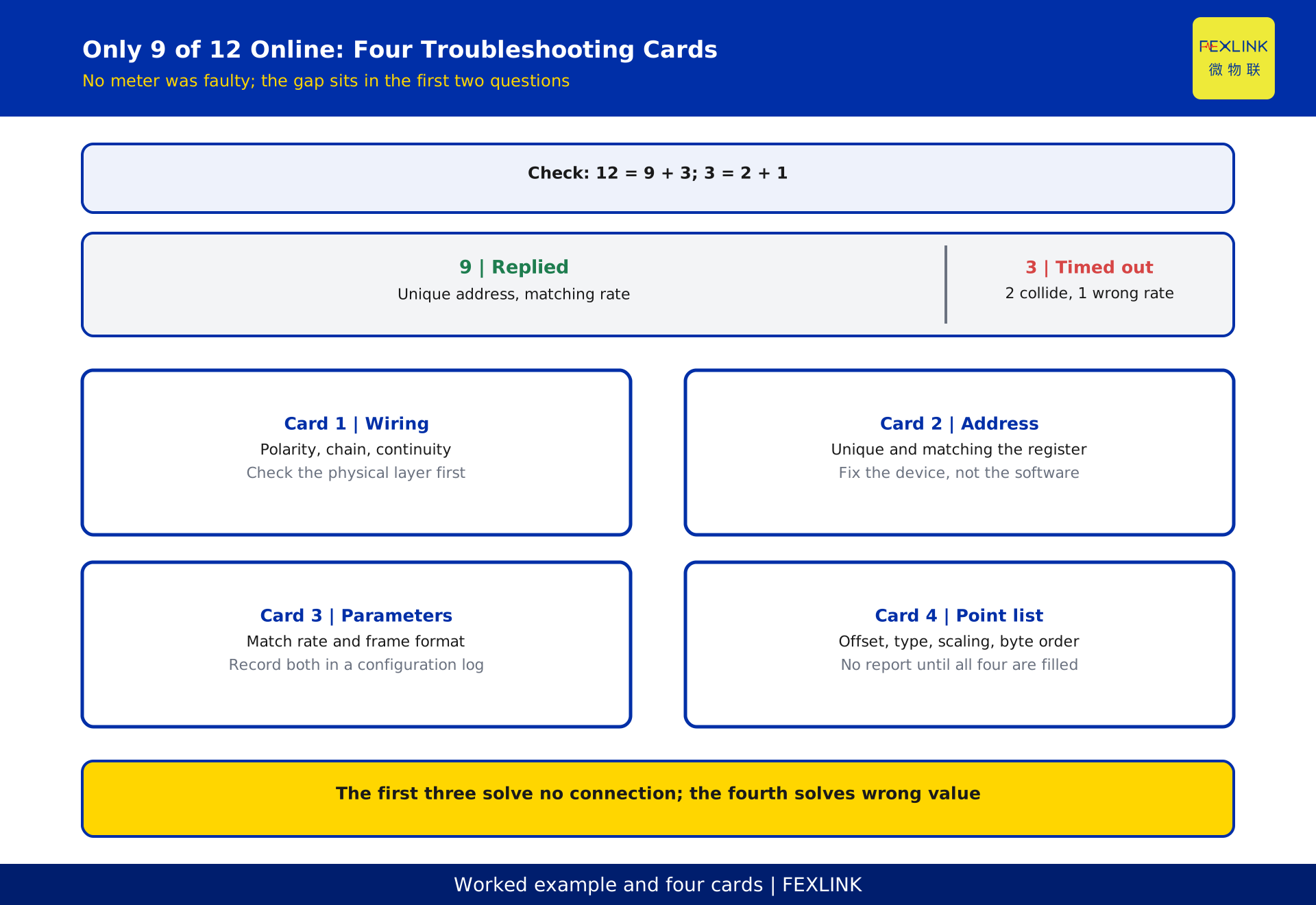
A distribution room had 12 meters on one bus. On the first day only 9 returned values and 3 kept timing out. A device-by-device check found that 2 meters shared one slave address, so their replies overlapped and the checksum failed; the remaining 1 used a different baud setting and could not recognise a frame boundary.
Check the arithmetic: 12 = 9 + 3 and 3 = 2 + 1. None of the three was faulty. After addresses and rate were corrected, all 12 replied, but one reading was clearly too large: the manual numbered positions from 1 while the gateway used offsets from 0, so everything shifted by 1 position. Two further agreements were missing, unit scaling and byte order, and that column stayed out of the report.
The classification stayed the same throughout: is there a reply, what does the reply say, and how is the number interpreted. The first three devices failed the first two questions, the last one the third. Restarting the gateway would not have fixed it. All figures here are constructed examples, anonymised, with no customer, location, project name or pricing.
9. Four troubleshooting cards
Card 1 | Wiring. Check that polarity is consistent, the chain is a chain, and continuity is sound. Termination and cabling practice belong to the physical-layer article, not here.
Card 2 | Address. Compare each device address with the master's address register for equality and uniqueness. An address collision is fixed on the device, not in the collector software.
Card 3 | Parameters. Check rate and frame format device by device and record both in a configuration register; if more than one master or gateway is present, first confirm that only one is issuing requests.
Card 4 | Point list. Once replies exist, verify the counting convention, data type, unit scaling and byte order. No report until all four columns are filled.
The order cannot be swapped: without frames there is nothing to address, with a wrong address the parameters cannot be judged, and with wrong parameters the point list should not be suspected. The first three cards solve "no connection", the fourth solves "wrong value". File the conclusions alongside the device register so the next meter need not start from scratch.
Frequently asked questions (FAQ)
Q: The RS-485 cable is connected, so why is there still no data on the platform?
A working cable only establishes the physical layer. You still need a unique slave address, matching baud rate and frame format, the right function code and starting position, and a point list that turns positions into engineering values. Follow the four cards in order.
Q: What happens if two meters share one address?
One request triggers two overlapping replies that fail the checksum. Those two devices appear intermittent while the others stay healthy. Change the address on the device; no meter or platform change is needed.
Q: Is a higher baud rate always better?
No. It only has to match at both ends, and the choice depends on bus conditions, cable quality and poll-cycle volume. Raising it blindly can make a stable long bus intermittent. Take the value from the device manual and the existing bus convention.
Q: Why does the number in the point list differ by 1 from the address in the frame?
Frames usually use an offset from 0, manuals number positions from 1, so the same position differs by one. Settle on one convention before configuring the gateway, then check data type, scaling factor and byte order. A one-position shift reads the neighbouring quantity; it is not a communication fault.
Q: If we switch meter brands, can we reuse the old point list?
The protocol concepts are generic, but the point list is device-specific. Which position holds what, in which format and at which scale must be rechecked against the new manual. Multi-vendor integration is covered in a neighbouring article.
Scope and limitations
This article is a conceptual introduction to Modbus RTU over RS-485: layering, master-slave polling, the four parts of a frame, registers and function codes, the four settings that must match, the four point-list columns and four troubleshooting cards. Physical-layer thresholds and device-count limits, cabling practice and termination values, the choice between DL/T 645 and other protocols, and frame capture to build a point list each belong to their own neighbouring article.
No standard clause numbers, fixed baud settings, address ceilings, termination resistances or checksum implementation details are given; engineering values come from device manuals, vendor point lists and current project documents. The figures of 12 meters, 9 online, 3 timing out, 12 = 9 + 3, 3 = 2 + 1, a one-position shift and 2 missing agreements are constructed, anonymised examples. This article is DRAFT_PENDING_REVIEW and requires independent review before publication; the generator does not self-approve.
Frequently Asked Questions
What Exactly Is Modbus over RS-485
A suffix like "-R (RS485/Modbus)" describes two different layers