 FEXLINK Research Institute
The short answer
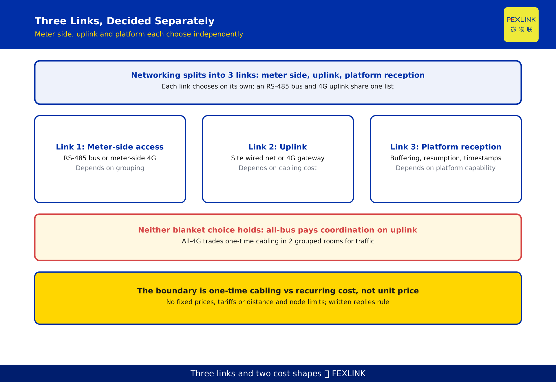
When meters are numerous and scattered, do not treat "RS-485 or 4G" as a one-time either-or choice. Split networking into three links and decide each separately: meter-side access from the meter to a local aggregation point, uplink from that point to the platform, and platform-side reception and resumption. For most campuses the answer is a hybrid - grouped meters run over an RS-485 bus into a gateway, and the gateway uplinks over 4G; only points that cannot be cabled, or that are temporary and cannot be grouped, uplink directly from the meter.
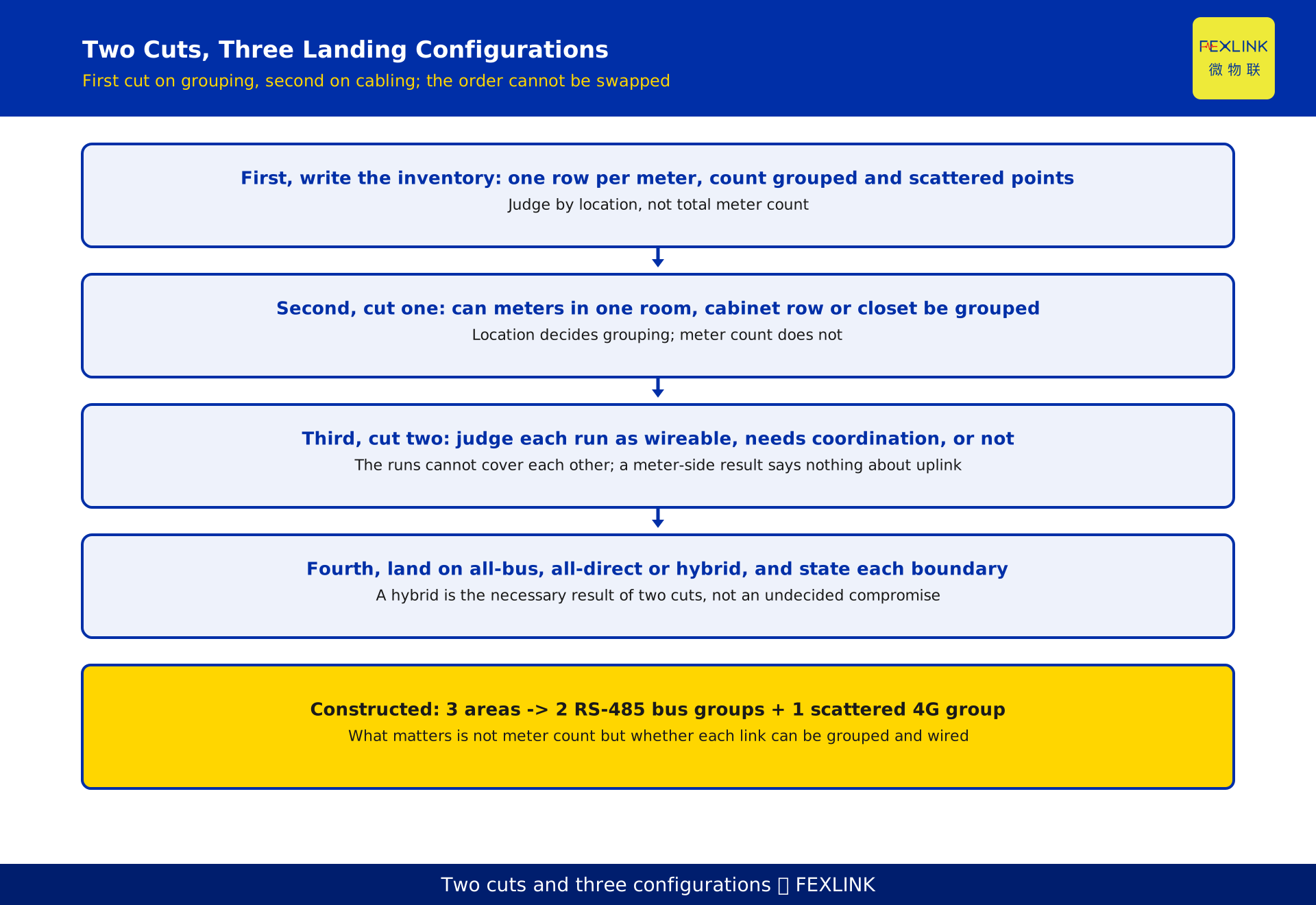
The order is: write a spatial inventory, judge whether each link can be wired and where the cabling cost falls, then set each link by "one-time cabling cost vs recurring traffic and maintenance cost". In the FEXLINK edge gateway and multi-protocol access family, bus meters, edge gateways and cellular gateways often share one quotation, yet belong to three links and are not interchangeable. This is a per-link decision method and a deployment checklist, not a tariff or distance table. Interface form, uplink mode and applicable conditions come from the nameplate, selection manual and written supplier response; published naming and tier descriptions are disclosure, not commitments.
1. Split "networking" into three links, not one binary choice
The most common mistake is to treat networking as one end-to-end channel from meter to platform, which forces a single choice for the whole project. It can be split into three links, each with its own constraints.
The first is meter-side access: how a meter reaches its aggregation point, governed by grouping and cabinet cabling conditions. The second is uplink: how data travels to the platform, governed by wired network availability, permission to lay lines, and cellular signal. The third is platform reception: how data is buffered during an outage and how timestamps align, governed by platform capability rather than the meter interface.
Each link chooses independently: the first over a bus, the second over cellular, the third handled uniformly by the platform. That is one design, not a compromise between two. Writing the three links as separate lines explains why one campus carries both bus meters and cellular gateways.
2. Two cost shapes: one-time cabling vs recurring traffic
The reason for splitting is that the cost shapes differ.
Cabling is mainly a one-time investment: cable, tray or conduit, installation and alterations, concentrated early and rising with distance and difficulty; once built, one more meter costs little. Cellular is mainly recurring: tariffs per direct point, local power or batteries, and site visits for scattered points, accumulating over time. It removes grouped cabling but spreads cost across the lifecycle.
The boundary is therefore not "which is cheaper" per unit, but "which link is worth a one-time cost for grouping". Dense, groupable meters amortise cabling across many meters; scattered meters, or sites with no cabling conditions, cannot amortise it, so direct uplink fits better. This article gives no fixed numbers for unit prices, tariffs, distance limits or node limits - those vary with site and contract, belong in the checklist, and must be confirmed against the model specification and site measurement.
3. First cut: grouped or scattered meters
The first cut asks one thing: can these meters be drawn into a few physically grouped aggregation points.
The criterion is location, not count. Meters in one distribution room, cabinet row or floor telecom closet group easily even when numerous; meters across buildings, floor ends or temporary additions do not, even when few. Write one row per meter with its location, whether it joins an aggregation point, and the resulting group size, then count groups and scattered points.
A common trap is concluding from the total count: a large total invites all-bus, yet a few scattered points pay for a whole cable run; a small total invites all-direct, yet tens of meters in one room each carry a subscription. Record group count and scattered points separately; this cut is spatial, not budget.
4. Second cut: can each link be wired, and who bears the cost
Being groupable does not make cabling worthwhile. The second cut asks whether each of the two physical runs - meter to aggregation point, aggregation point to platform - can be wired, and who carries the cost.
The meter-side run is usually short and manageable inside a cabinet or one room, but depends on existing conduit, drilling and outage permission, and future expansion. The uplink run is often dearer: across buildings or roads and through finished areas, coordination may cost far more than the cable; even with a bus on the meter side, uplink need not be wired.
Judge the two separately: a wireable meter side does not imply a wireable uplink, nor does a wired network imply groupable meters. Record each as "wireable / needs coordination / not wireable" with a reason; when the last two fall outside the acceptable range, that link moves to direct uplink. Conclusions on power, signal coverage and conduit come from site survey and written supplier response.
5. Two cuts, three landing configurations
Combining the two cuts lands on three configurations.
All-bus: every meter can be grouped and both runs wired; the meter side uses an RS-485 bus to a gateway and uplink uses the existing wired network, suiting a single distribution room or a new site with conduit in one pass. All-direct: meters are scattered and neither grouping nor cabling holds, so each point uplinks on its own, suiting temporary metering, short leases or buildings where work is impossible. Hybrid: the real shape of most sites - groupable meters run over a bus into an edge gateway, and the gateway uplinks over 4G; a few scattered or non-wireable points uplink directly alongside the bus groups.
Do not dismiss the hybrid as an undecided compromise. It is the necessary result of two cuts landing differently on different links, and the checklist must state which link uses which mode and where each boundary lies. These three configurations describe how links are built; they promise no communication interface, uplink standard or tariff for any model.
6. Landing a hybrid design: group, uplink, platform
Deploy in four steps, in this order.
Step one groups: divide meters by location into aggregation groups, each with count, position, power condition and assigned gateway. Step two sets the meter side: grouped meters chain over a bus to their gateway, with addresses, polarity and termination checked group by group; scattered points are listed separately. Step three sets the uplink: judge each gateway independently - use the site wired network where available, otherwise a cellular gateway, and record signal and power conditions in the survey. Step four aligns the platform: bring all groups and scattered points under one naming, timestamp and outage-resumption convention, avoiding two reconciliation times.
Node counts, distances and polling cycles are not given as fixed numbers; how many devices a bus carries, how segments are divided and whether uplink bandwidth suffices are commissioning checks against the model specification and site measurement. The FEXLINK edge gateway and multi-protocol access family consumes already-grouped data.
7. Suffixes and ordering: a marker is not a network design
Suffixes such as -R and -G on a selection sheet are often read as the answer to "bus or 4G". That is a misreading. A suffix is only a marker for checking device interface and uplink configuration at order time, part of a vendor-disclosed naming convention; one project can quite legitimately carry both suffixes because the three links choose independently.
The correct practice is to turn every checklist line into a verifiable order item: interface type, uplink mode, power condition, applicable environment and items needing written confirmation per link, with the supplier stating the model item by item against the selection manual and replying in writing under a register confirmation reference. Nothing unverified may be inferred from a suffix, and no suffix is a network design. Vendor-disclosed naming is an ordering reference only; capability comes from the nameplate, selection manual and written supplier response.
8. Worked example: 3 metering areas
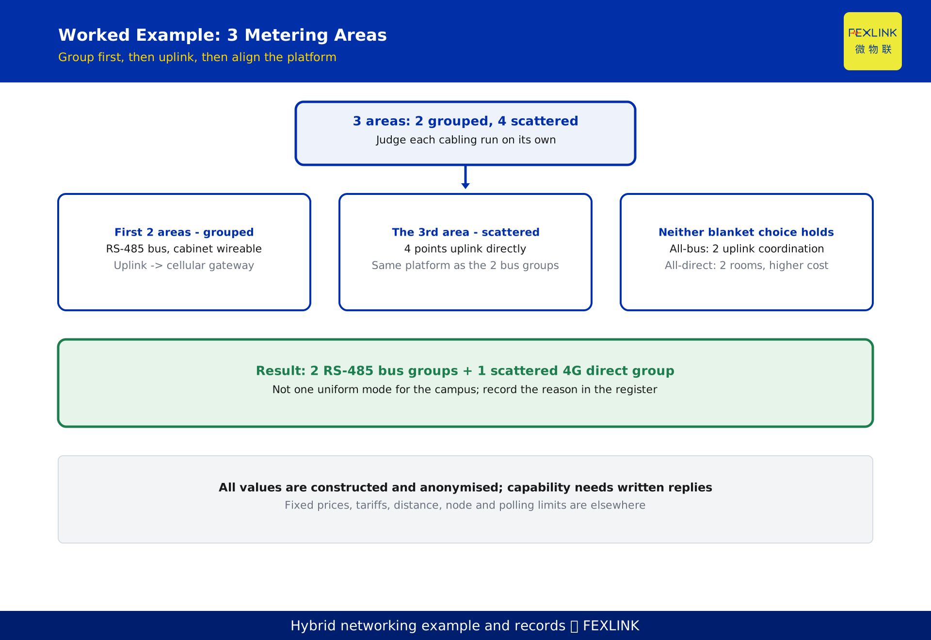
The following is a constructed, de-identified example and represents no real customer or project. A campus adds 3 metering areas: in 2 distribution rooms the meters group locally, while in the 3rd area meters are spread across 4 floor-end points.
The first 2 areas become two aggregation groups: the meter side chains over a bus to each gateway, with controllable in-cabinet cabling judged wireable; the uplink crosses buildings through finished areas and is judged as needing coordination, so both groups use cellular gateways to reach the platform directly. The 3rd area cannot be grouped, so its 4 points uplink directly and join the same platform alongside the two bus groups. The result is a hybrid of "2 bus groups + 1 scattered direct group", not one uniform mode for the whole campus.
Neither blanket choice holds. All-bus would pay coordination cost for 2 cross-building uplink runs unrelated to meter count, and the 4 points in the 3rd area cannot group at all. All-direct would leave the grouped meters in 2 distribution rooms each carrying recurring traffic and site visits, trading amortisable one-time cabling for long-term cost. What matters is not the meter count but whether each link can be grouped and wired.
9. The networking register: keep the per-link reasoning
Keep one row per aggregation group with at least four columns: group ID and location, meter count and grouping basis, the two wiring judgements (meter side / uplink), and the chosen access mode per link with its written confirmation reference. Scattered points get their own rows with the reason they cannot group; append power and signal survey results and the platform naming and timestamp convention.
The register pays off at expansion and fault-finding: a new meter is checked against existing groups rather than reopening the selection sheet, and an abnormal group is traced in "meter side - uplink - platform" order, so an uplink fault is not misdiagnosed as a meter fault. The upstream system consumes an already-selected link and cannot recreate a segment the front end never collected. At review or audit, four columns reconstruct why the links were split - something no parameter table replaces.
Frequently Asked Questions (FAQ)
Q: All meters are in one distribution room; can we ignore 4G entirely?
The meter side can largely be set to a bus, but the uplink still needs its own judgement. With no usable wired network on site, and cross-zone work not permitted, the gateway may still need a cellular uplink. The three links choose independently; a meter-side conclusion cannot be extended to the uplink.
Q: Is going all-4G the simplest, with lighter maintenance later?
It removes one-time cabling but adds per-point tariffs, power and site visits at scattered locations. Where meters are dense and grouped, these recurring costs accumulate with point count and faults must be chased point by point. Whether it is lighter depends on grouping, not on the interface itself.
Q: How many meters can an RS-485 bus carry, and how far?
This article gives no fixed number. Device count, segment division, distance and termination vary with model, cable and site conditions; they must be confirmed in writing against the model specification and checked by site measurement during commissioning, not settled by one sentence at selection stage.
Q: Does a -G suffix mean that point must use 4G direct uplink?
No. A suffix is an ordering marker for checking interface and uplink configuration under a vendor-disclosed naming convention; a cellular gateway can perfectly well carry data already aggregated over a bus, which is exactly the common hybrid shape. Concrete configuration follows the selection manual and written replies.
Q: The supplier says verbally that "both work". How do we confirm?
Turn the three links into verifiable items line by line, require a written statement of model, interface type, uplink mode, applicable conditions and power requirements, and record it under a register confirmation reference. Vendor tier descriptions are a family reference only and do not enter the networking conclusion; written replies, survey records and commissioning acceptance are the review basis.
Scope and limitations
This article is a per-link decision method for networking distributed meters in the preparation stage of metering system selection on campuses, buildings and distribution rooms; it does not replace engineering design, current standards, communication surveys or the selection manual. The three configurations and the suffix discussion are vendor-disclosed family summaries and naming conventions, not a commitment about any model's interface, uplink standard, capacity, tariff or outcome. Interface form, bus device count, transmission distance, signal coverage and power conditions are governed by the nameplate, selection manual, site survey and written supplier response. No numeric comparisons of unit prices, tariffs, distance limits, node limits or polling cycles are given; system-wide layering, gateway capacity estimation and outage root-cause analysis belong to dedicated articles. The worked example is constructed and de-identified and represents no real customer or project. All deliverables remain DRAFT_PENDING_REVIEW and require independent review; the generator does not self-approve.
Frequently Asked Questions
RS-485 Bus or 4G Direct
When meters are numerous and scattered, do not treat "RS-485 or 4G" as a one-time either-or choice